SERVICE MANUAL UPDATE SEC. 6A2 OIL PUMP INSTALL/INSPECT

Subject: OIL PUMP REMOVAL
Model and Year: 1990-91 GEO PRIZM GSI ONLY
This bulletin cancels and supersedes the "Oil Pump" procedure and Figures 25 through 28 beginning on page 6A2-21 of the 1991 GEO Prizm Service Manual (ST373-91). This bulletin also cancels and supersedes the "Oil Pump" procedure and Figures 27 through 30 beginning on page 6A2-20 of the 1990 GEO Prizm GSi Service Manual Supplement (ST373-90 Supp.) Whenever service is required to the oil pump of a GEO Prizm GSi model, refer to this service bulletin.
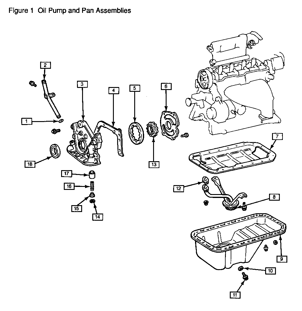
SEE FIGURE 1
[1] O-RING [2] OIL INDICATOR (DIPSTICK) GUIDE TUBE [3] OIL PUMP BODY [4] OIL PUMP GASKET [5] DRIVEN GEAR [6] OIL PUMP COVER [7] OIL BAFFLE [8] OIL STRAINER [9] OIL PAN [10] DRAIN PLUG GASKET [11] DRAIN PLUG [12] OIL STRAINER GASKET [13] DRIVE GEAR [14] SNAP RING [15] RETAINER [16] SPRING [17] RELIEF VALVE [18] OIL SEAL
Oil Pump Figures 1 through 6
Remove or Disconnect
1. Battery negative (-) cable.
2. Timing belt. Refer to "Timing Belt and Camshaft Timing Pulleys" in Section 6A2 in the 1991 GEO Prizm Service Manual (ST373-91).
* Raise and suitably support vehicle. Refer to General Information (Section OA) in the 1991 GEO Prizm Service Manual (ST373-91).
3. Crankshaft pulley. Refer to "Crankshaft Pulley" in Section 6A2 in the 1991 GEO Prizm Service Manual (ST373-91).
4. Front exhaust pipe. Refer to Exhaust System (Section 6F) in the 1991 GEO Prizm Service Manual (ST373-91).
5. Oil pan. Refer to "Oil Pan" in Section 6A2 in the 1991 GEO Prizm Service Manual (ST373- 91).
6. Oil baffle. Carefully break sealant and remove baffle from engine block.
7. Oil strainer from oil pump (two bolts and two nuts).
8. Seven oil pump mounting bolts.
9. Oil pump from crankshaft by tapping with a plastic hammer.
10. Oil pump gasket from engine block.
Clean
* Oil pump gasket mating surfaces.
Disassemble
1. Oil pump cover from back of pump body (five screws).
2. Oil pump relief valve.
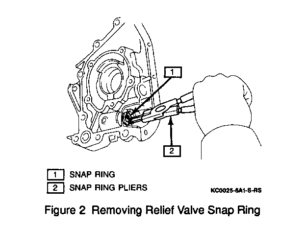
A. Remove snap ring with snap ring pliers (Figure 2).
B. Remove retainer, spring and relief valve from oil pump body (Figure 1).
3. Crankshaft oil seal from oil pump using a screwdriver.
Measure
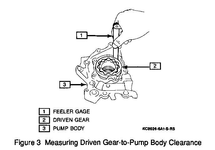
* Oil pump driven gear to housing clearance using a feeler gage. If the clearance is more than 0.20 mm (0.0079 inch), replace the oil pump (Figure 3).
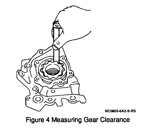
* Oil pump drive gear to driven gear clearance using a feeler gage. If the clearance is more than 0.33 mm (0.01 38 inch), replace the gear set (Figure 4).
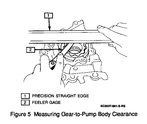
* Oil pump body to gear clearance using a feeler gage with a precision straightedge. If the clearance is more than 0.10 mm (0.0039 inch), replace the oil pump (Figure 5).
Assemble
Tool Required:
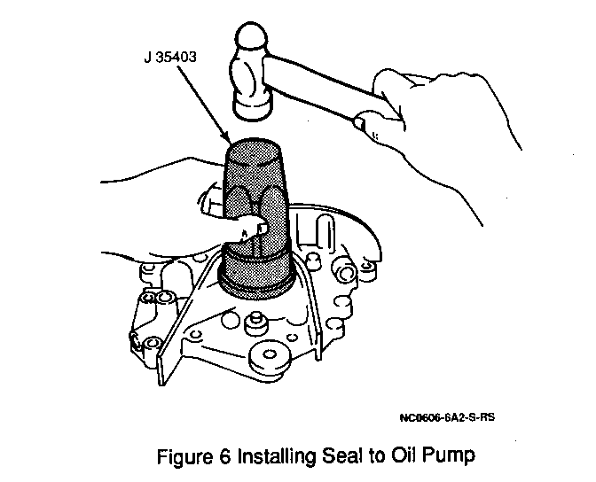
J 35403 Oil Pump Seal Installer
1. Oil pump cover; secure with five screws.
2. Relief valve, spring, retainer and snap ring.
3. New oil seal using a J 35403 oil pump seal installer (Figure 6).
Install or Connect
Apply GM #1 052917, or equivalent sealant to the oil pump gasket surface.
1. Oil pump and new gasket onto cylinder block; secure with seven bolts.
Tighten
Oil pump mounting bolts to 21 N.m (1 6 lbs. ft.).
2. Oil strainer to oil pump (two bolts and two nuts).
Tighten
* Oil strainer nuts and bolts to 1 0 N.m (89 lbs. inch). * Apply a 3-5 mm (0.12 - 0.20 inch) bead of GM #1052917 or equivalent sealant to the perimeter of the oil baffle.
NOTICE: AVOID APPLYING SEALING COMPOUND TOO HEAVILY, PARTICULARLY NEAR OIL PASSAGES. EXCESS SEALING COMPOUND COULD BLOCK OIL FLOW THROUGH THE PASSAGES AND CAUSE ENGINE DAMAGE.
3. Oil baffle to engine block.
4. Oil pan. Refer to "Oil Pan" in Section 6A2 in the 1991 GEO Prizm Service Manual (ST373- 91).
5. Front exhaust pipe. Refer to Exhaust System (Section 6F) in the 1991 GEO Prizm Service Manual (ST373-91).
6. Crankshaft pulley. Refer to "Crankshaft Pulley" in Section 6A2 in the 1991 GEO Prizm Service Manual (ST373- 91).
* Lower vehicle.
7. Timing belt. Refer to "Timing Belt and Camshaft Timing Pulleys" in Section 6A2 in the 1991 GEO Prizm Service Manual (ST373-91).
8. Battery negative (-) cable.
General Motors bulletins are intended for use by professional technicians, not a "do-it-yourselfer". They are written to inform those technicians of conditions that may occur on some vehicles, or to provide information that could assist in the proper service of a vehicle. Properly trained technicians have the equipment, tools, safety instructions and know-how to do a job properly and safely. If a condition is described, do not assume that the bulletin applies to your vehicle, or that your vehicle will have that condition. See a General Motors dealer servicing your brand of General Motors vehicle for information on whether your vehicle may benefit from the information.
