For 1990-2009 cars only
Removal Procedure
- Remove the instrument panel (I/P) upper trim panel. Refer to Instrument Panel Upper Trim Panel Replacement .
- Remove the I/P outer trim covers. Refer to Instrument Panel Outer Trim Cover Replacement .
- Remove the I/P compartment. Refer to Instrument Panel Compartment Replacement .
- Remove the knee bolster. Refer to Knee Bolster Replacement .
- Remove the cluster trim bezel assembly. Refer to Instrument Panel Cluster Trim Plate Bezel Replacement .
- Remove the cluster. Refer to Instrument Cluster Replacement .
- Remove the I/P center trim panel. Refer to Instrument Panel Center Trim Panel Replacement .
- Remove the HVAC control module. Refer to HVAC Control Module Replacement in Heating, Ventilation, and Air Conditioning.
- Remove the radio. Refer to Radio Replacement in Entertainment.
- Remove the ignition switch wire harness connectors. Refer to Ignition and Start Switch Replacement .
- Remove the park lock cable at the ignition switch. Refer to Park Lock Cable Replacement in Automatic Transaxle - 4T40-E/4T45-E.
- Remove the accessory switch assembly. Refer to Accessory Switch Replacement .
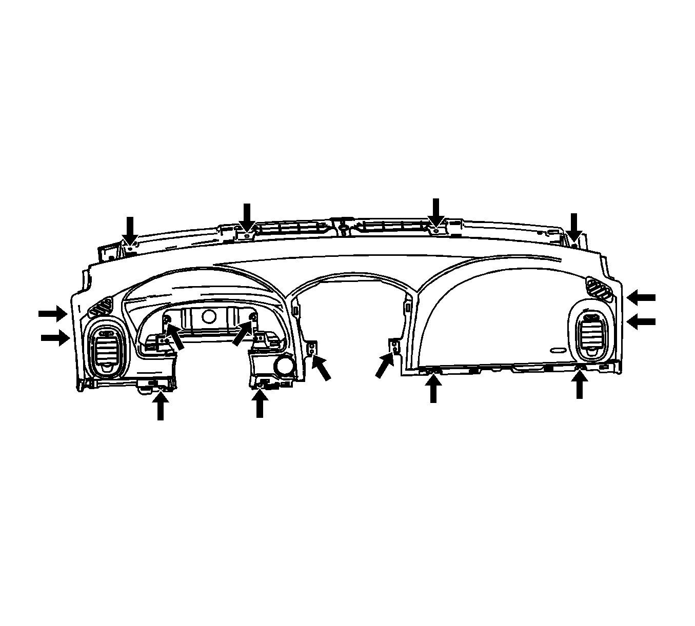
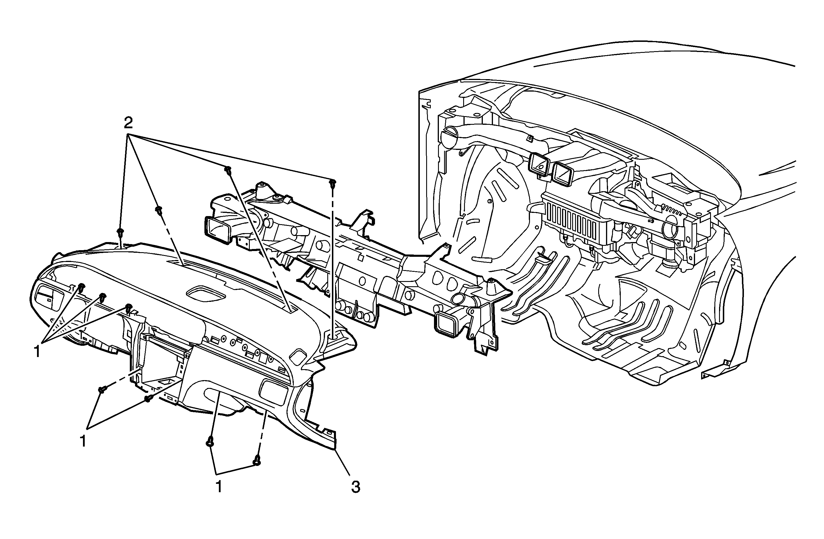
- Remove the I/P trim pad screws.
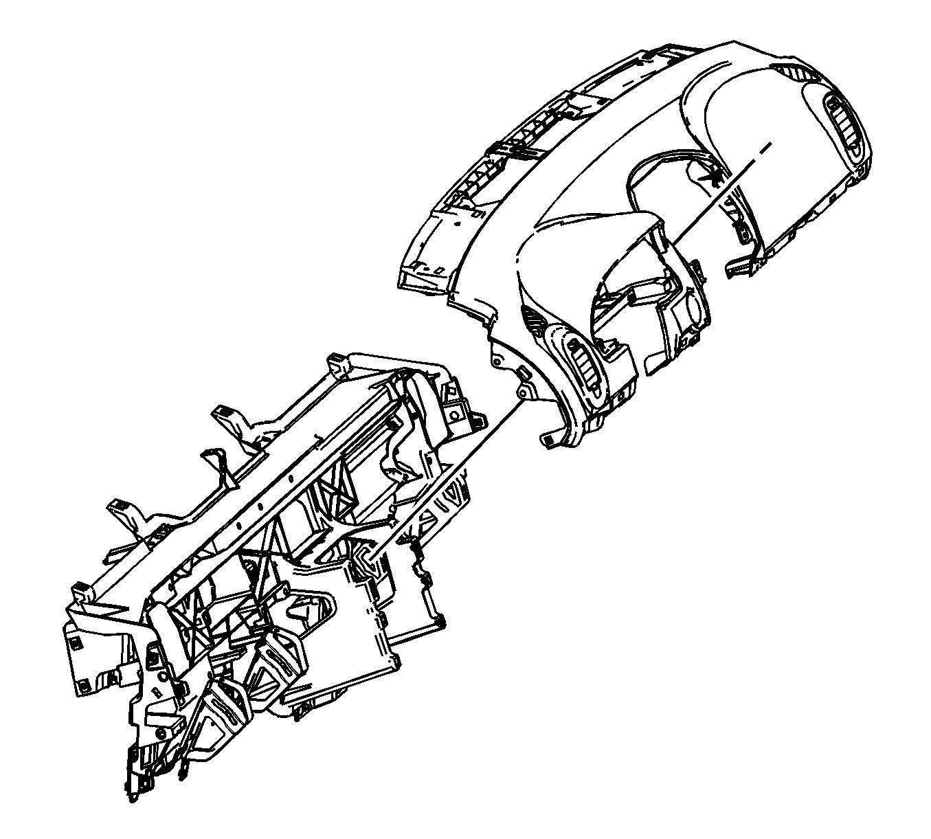
- Remove the I/P pad.
- Remove the ignition switch from the I/P pad. Refer to Ignition and Start Switch Replacement .


Installation Procedure
- Install the ignition switch from the I/P pad. Refer to Ignition and Start Switch Replacement .
- Install the I/P pad.
- Tighten the I/P trim pad screws.
- Install the park lock cable at the ignition switch. Refer to Park Lock Cable Replacement in Automatic Transaxle - 4T40-E/4T45-E.
- Install the ignition switch wire harness connectors. Refer to Ignition and Start Switch Replacement .
- Install the radio. Refer to Radio Replacement in Entertainment.
- Install the HVAC control module. Refer to HVAC Control Module Replacement in Heating, Ventilation and Air Conditioning.
- Install the accessory switch assembly. Refer to Accessory Switch Replacement .
- Install the I/P center trim panel. Refer to Instrument Panel Center Trim Panel Replacement .
- Install the cluster. Refer to Instrument Cluster Replacement .
- Install the cluster trim bezel assembly. Refer to Instrument Panel Cluster Trim Plate Bezel Replacement .
- Install the knee bolster. Refer to Knee Bolster Replacement .
- Install the I/P compartment. Refer to Instrument Panel Compartment Replacement .
- Install the I/P outer trim covers. Refer to Instrument Panel Outer Trim Cover Replacement .
- Install the I/P upper trim panel. Refer to Instrument Panel Upper Trim Panel Replacement .

Notice: Refer to Fastener Notice in the Preface section.

Tighten
Tighten the screws to 2.5 N·m (22 lb in).

Callout | Component Name |
|---|---|
|
Notice: Refer to Fastener Notice in the Preface section. Fastener Tightening Specifications: Refer to Fastener Tightening Specifications . Preliminary Procedures
| |
1 | Instrument Panel Trim Pad Screws (Qty: 7) Tighten |
2 | Instrument Panel Trim Pad Screws (Qty: 4) Tighten |
3 | Instrument Panel Trim Pad Assembly |
