Power Take-Off (PTO) Inoperative or Not Operating Properly (Check TCM Feedback Signal, Modify Wiring If Necessary)

| Subject: | Power Take-Off (PTO) Inoperative or Not Operating Properly (Check TCM Feedback Signal, Modify Wiring If Necessary) |
| Models: | 2006 Chevrolet Kodiak C4500-C7500 Series |
| 2006 GMC TopKick C4500-C7500 Series |
| with 6.6L Duramax™ Diesel Engine (VIN 2 - RPO LLY) or 8.1L Gas Engine (VIN G - RPO L18) and Allison 1000/2200/2300 Series Transmission (RPOs M74, MB7, MB8, MD1, MTX, MTY) |
This bulletin is being revised to include additional Correction information. Please discard Corporate Bulletin Number 06-08-131-001 (Section 08 - Body & Accessories).
Condition
Some customers or vehicle upfitters may comment that the power take-off is not operating properly with the transmission in park or neutral and PTO ON under load, or that there is a "chattering" solenoid type noise coming from the transmission after PTO installation.
Cause
The transmission control module (TCM) may be damaged as a result of the wiring harness not being correct for PTO applications on the affected vehicles.
Correction
Important: This procedure only applies to 2006 model year vehicles. 2005 and prior vehicles are NOT affected.
Diagnosis
Determine if the wiring harness has been previously modified by performing the following test on the system:
8.1L V-8 (L18) Engine Equipped Trucks:
- With the ignition OFF, disconnect the TCM connector (80-way) and locate terminal 21.
- Disconnect PCM connector J1 and locate terminal 52.
- Using the proper probe tools, use a Digital Multimeter and check for continuity between TCM terminal 21 and PCM terminal 52.
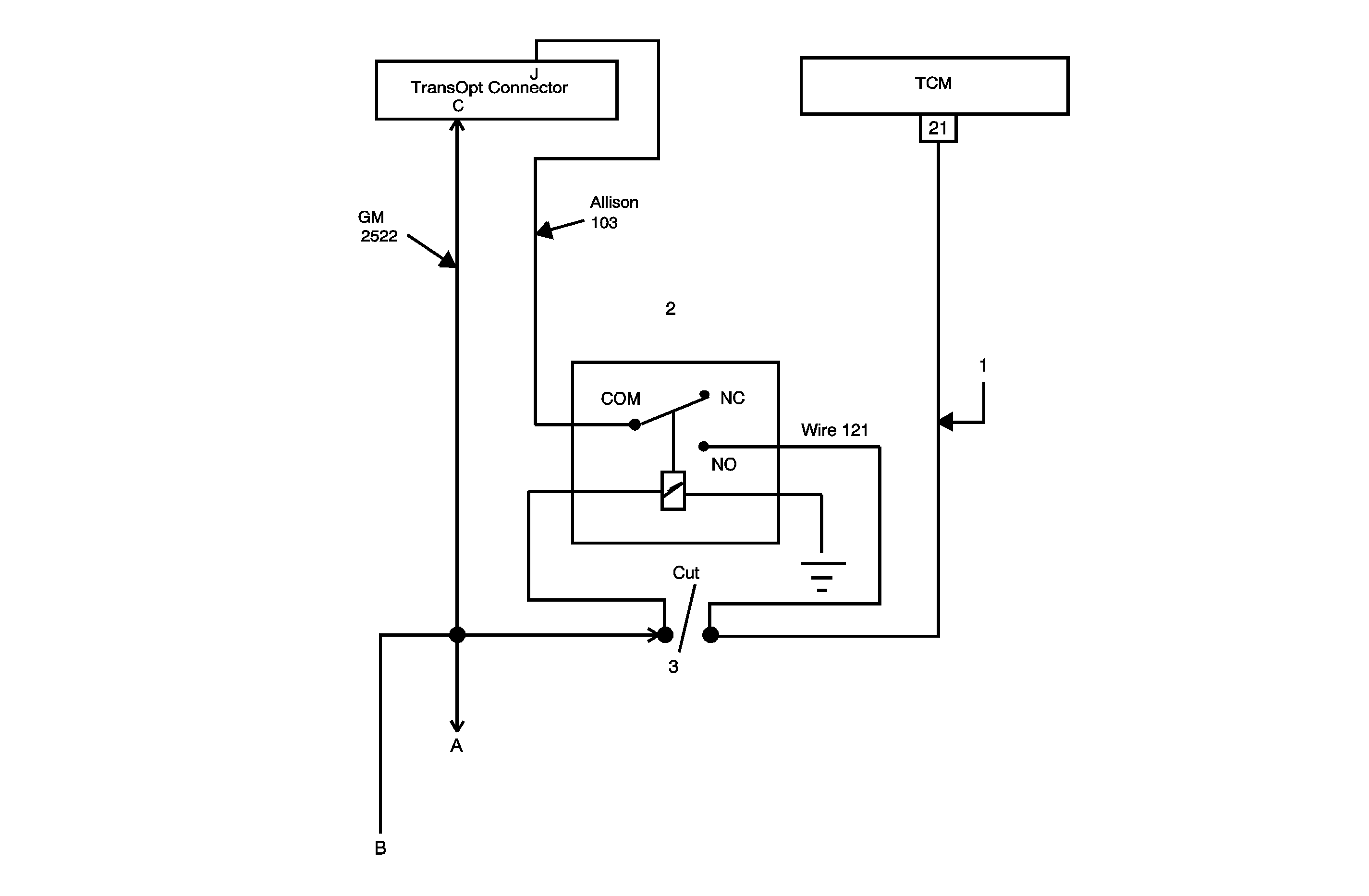
- If there is continuity, the system must be modified and a relay installed as shown in the Feedback Circuit Modification Procedure below.
- If there is no continuity, refer to the Feedback Circuit Modification Procedure below and determine if the modification was done properly and correct if necessary. If modified properly, the concern is not related to the feedback circuit. Contact the PTO Manufacturer or GM Upfitter Integration for assistance. Refer to www.gmupfitter.com or call (800) 875-4742 to contact GM Upfitter Integration.
- If the PTO was installed and operated prior to the wiring modifications below, replace the TCM AFTER circuit modifications are complete. Refer to "Transmission Control Module Replacement" procedure in SI for the appropriate type of transmission. (The original wiring provided 12 V to the TCM each time the PTO was engaged. This may have damaged the original TCM.)
6.6L V-8 Diesel (LLY) Engine Equipped Trucks:
- With the ignition OFF, disconnect the TCM connector (80-way) and locate terminal 21.
- Disconnect PCM connector J1 and locate terminal 08.
- Using the proper probe tools, use a Digital Multimeter and check for continuity between TCM terminal 21 and PCM terminal 08.
- If there is continuity, the system must be modified and a relay installed as shown in the Feedback Circuit Modification Procedure below.
- If there is no continuity, refer to the Feedback Circuit Modification Procedure below and determine if the modification was done properly and correct if necessary. If modified properly, the concern is not related to the feedback circuit. Contact the PTO Manufacturer or GM Upfitter Integration for assistance. Refer to www.gmupfitter.com or call (800) 875-4742 to contact GM Upfitter Integration.
- If the PTO was installed and operated prior to the wiring modifications below, replace the TCM AFTER circuit modifications are complete. Refer to "Transmission Control Module Replacement" procedure in SI for the appropriate type of transmission. (The original wiring provided 12 V to the TCM each time the PTO was engaged. This may have damaged the original TCM.)
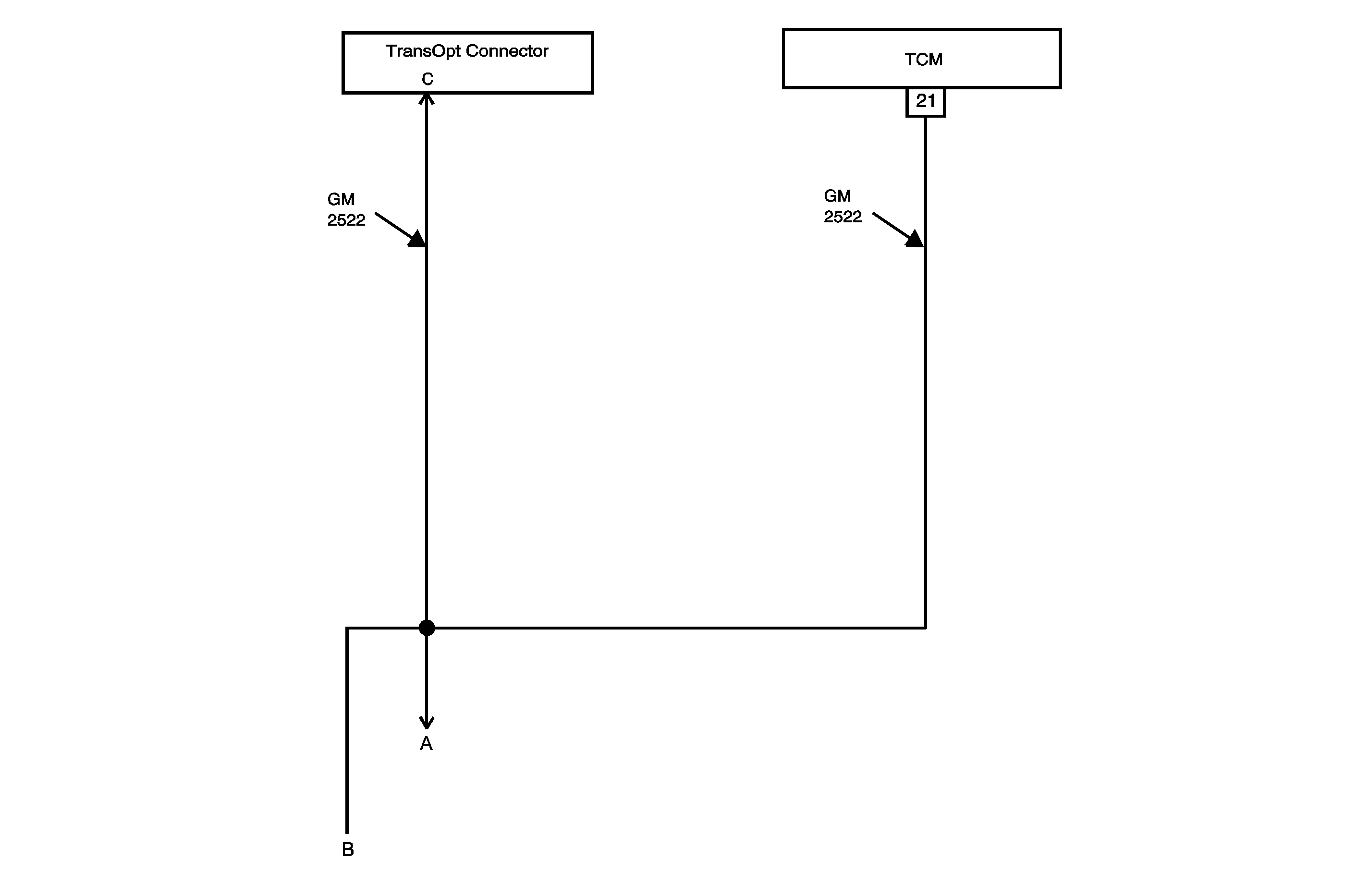
2006 Kodiak/TopKick PTO and Neutral Lockup Wiring - Allison 4th Generation Controls (As Received/Pre-Rework)

The illustration above shows the PTO feedback circuit for vehicles as built from the factory, without the required modifications. "A" is the PTO feedback to the ECM/PCM. "B" is Pin G of the Upfitter Connector on the vehicle harness (wire 2522).
Feedback Circuit Modification Procedure

