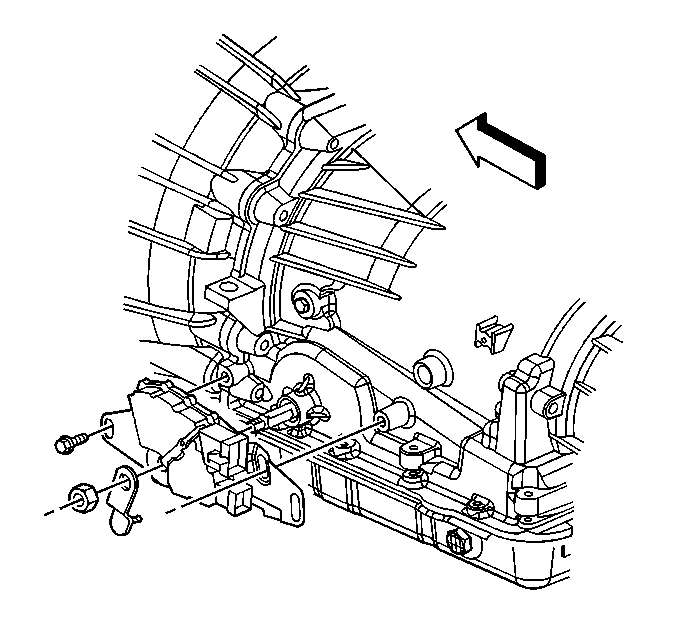
Removal Procedure
- Apply the parking brake.
- Shift the transmission into neutral.
- Remove the nut securing the transmission control lever to the manual shaft.
- Remove the transmission control lever from the manual shaft.
- Disconnect the wiring harness connector at the wiring harness.
- Remove two bolts securing the park/neutral position switch to the transmission.
- Remove the park/neutral position switch from the manual shaft.

Important: Because of the park neutral position switch lead connector breaking when disconnected, disconnect the harness connector at a point near the vehicle harness, not at the park neutral position switch lead.
Installation Procedure
- If the park/neutral position switch did not slide off the manual shaft, file the outer edge of the manual shaft in order to remove any burrs.
- Install the switch to the transmission manual shaft by aligning the switch hub flats with the manual shaft flats.
- Slide the switch onto the transmission manual shaft until the switch mounting bracket contacts the mounting bosses on the transmission.
- Install the switch to the transmission with two bolts.
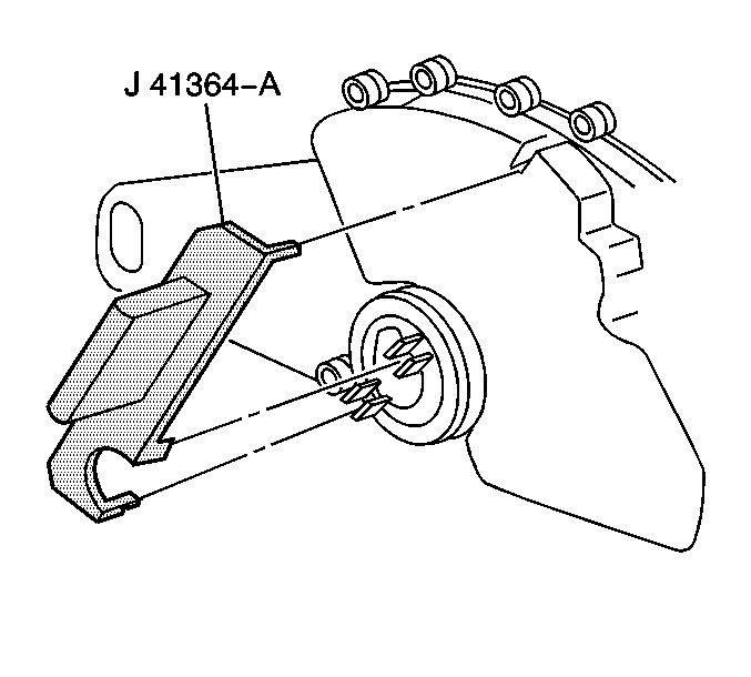
- Position the tool J 41364-a onto the park/neutral position switch. Ensure that the two slots on the switch where the manual shaft is inserted are lined up with the lower two tabs on the tool.
- Rotate the tool until the upper locator pin on the tool is lined up with the slot on the top of the switch.
- Remove J 41364-a from the switch.
- Install the wiring harness connector at the vehicle harness.
- Install the transmission control lever to the manual shaft with the nut.
- Lower the vehicle.
- Check the switch for proper operation. The engine must start in the P (Park) or N (Neutral) positions only. If adjustment is required.

Do not tighten the bolts.

Notice: Use the correct fastener in the correct location. Replacement fasteners must be the correct part number for that application. Fasteners requiring replacement or fasteners requiring the use of thread locking compound or sealant are identified in the service procedure. Do not use paints, lubricants, or corrosion inhibitors on fasteners or fastener joint surfaces unless specified. These coatings affect fastener torque and joint clamping force and may damage the fastener. Use the correct tightening sequence and specifications when installing fasteners in order to avoid damage to parts and systems.
Tighten
Tighten the bolts securing the switch to 25 N·m (18 lb ft).

Tighten
Tighten the control lever nut to 25 N·m (18 lb ft).
