DEALER INSTALLED ANCHOR CHILD SEAT WITH TOP STRAP

Models: 110 & 125 Inch Wheelbase "G" Vans, Caballero, S-T Pickups, Extended Cabs & Jimmy's & C-K Trucks
Note: All hardware discussed in this bulletin should be supplied or available from the child seat manufacturer. Be sure the child seat position does not conflict with any additional requirements provided by its manufacturer, or with any recommendations in the Child Restraint section of the Owner's Manual.
The child seat may be used only in a forward facing seating location. However, installation is not recommended in the front passenger seat of "G" Vans. The second seat offset to allow passenger entry does not position a second seat lap belt within the recommended zone for attachment to the top strap hook. Moreover, a floor anchorage is impractical since the top strap length is insufficient to directly connect the restraint to the floor with high back bucket seats.
For all 125 Inch Wheelbase "G" Vans Locations Recommended
Second Seat - When vehicle is equipped with a third seat: All seating positions.
Use Child Seat as directed in the usage instructions furnished with the Child Seat, latching the Child Seat top strap hook to the third seat lap belt tongue located most directly behind the Child Seat.
Second Seat - When vehicle does not hoave a third seat - all seating positions.
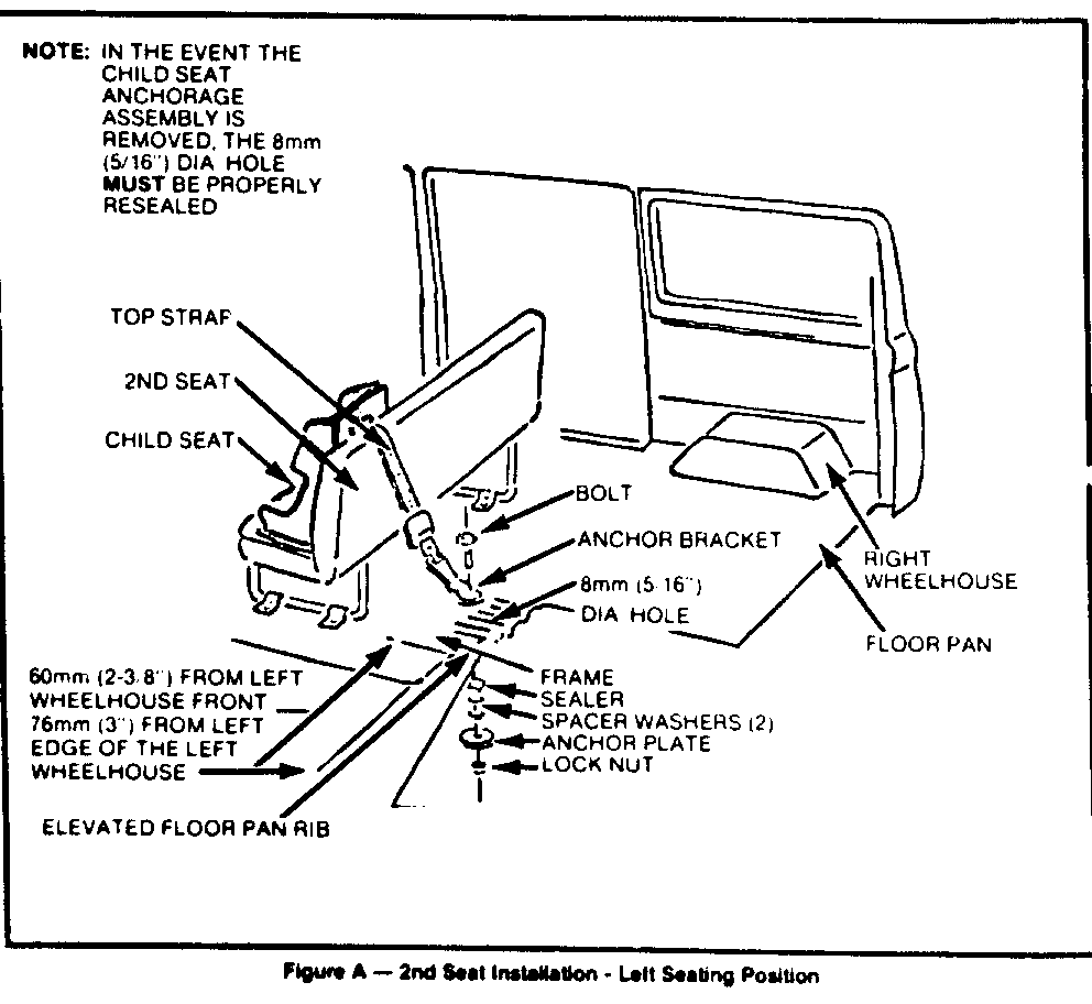
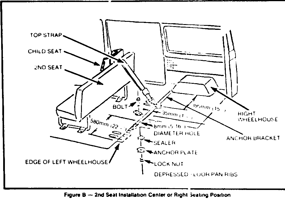
Install the anchor bracket in accord with the instructions on Pages 2 and 3 (Refer to Figures A and B)
Third Seat - When vehicle is equipped with a fourth seat - All seating positions.
Use the Child Seat as directed in the usage instructions furnished with the Child Seat, latching the Child Seat top strap hook to the fourth seat lap belt tongue located most directly behind the Child Seat.
Third Seat - When vehicle does not have a fourth seat - Only recommended for use in left seating position (Not recommended for center or right positions).
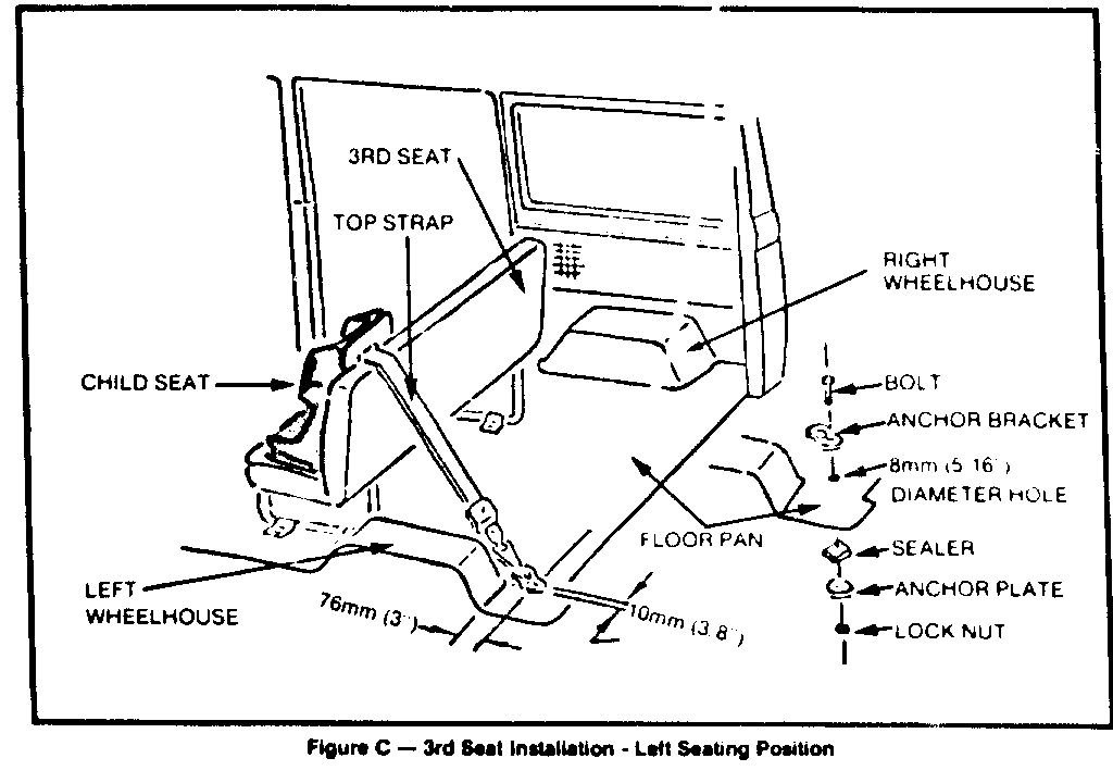
Install the anchor bracket in accord with the instructions on Page 2. Refer to Figure C.
Fourth Seat - Not recommended.
Note: In the event the child seat anchorage assembly is removed, the 8mm (5/16") diameter hold must be properly resealed.
Second Seat Installation Instructions - When Vehicle Does Not Have a Third Seat
Left Seeing Position:
1. Drill an 8mm (5/16") diameter hole through the floor pan 76mm (3") rearward of the front edge of the left wheelhouse on the center of the elevated floor pan rib located 60mm (2-3/8") inboard of the left wheelhouse. Refer to Figure A.
2. To insure proper sealing of the hole, remove any dirt or foreign matter from around the hole on the underside of the floor pan where the sealer is to be applied.
3. Place sealer on the hole from the underside of the vehicle and assemble the bolt anchor bracket two 35mm (1-3/8") O.D. spacer washers, anchor plate and lock nut to the floor pan as shown in Figure A. Tighten securely and make certain that the hole is completely sealed.
4. Use the Child Seat in the second seat - left seating position as directed in the usage instructions, latching the Child Seat top strap hook to the anchor bracket.
Center or Right Seating Positions
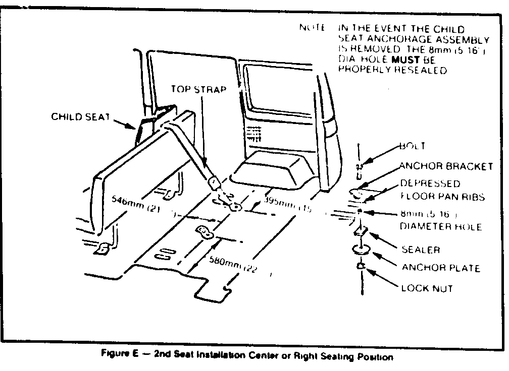
1. Center Seating Position - Drill an 8mm (5/16") diameter hole through the floor pan 35mm (1-3/8") rearward of the front edge of the left wheelhouse and on the center of the depressed floor pan rib located 580mm (22 7/8") inboard of the right wheelhouse. Refer to Figure B.
OR
Right Seating Position - Drill an 8mm (5/16") diameter hole through the floor pan 35mm (1- 3/8") rearward of the front edge of the right wheelhouse and on the center of the depressed floor pan rib located 395mm (15-1/2") inboard of the right wheelhouse. Refer to Figure B.
2. To insure proper sealing of the hole, remove any dirt or foreign matter from around the hole on the underside of the floor pan where the sealer is to be applied.
3. Place sealer the hole from underside of the vehicle and assemble the bolt, anchor bracket, anchor plate and lock nut to the floor pan as shown in Figure B. Tighten securely and make certain that the hole is completely sealed. Note: The two 35mm (1-3/8") O.D. spacer washers are not needed for these installations.
4. Use the Child Seat in the seating position of the second seat for which the anchor bracket has been installed. Use the Child Seat as directed in the usage instructions, latching the Child Seat top strap hook to the anchor bracket.
THIRD SEAT INSTALLATION INSTRUCTIONS - WHEN VEHICLE DOES NOT HAVE A FOURTH SEAT - Refer to Figure C.
Only recommmended in Left Seating Position
Left Seating Position
1. Drill an 8mm (5/16") diameter hole through the floor pan 76mm (3") rearward and 10mm (3/8") inboard of the left wheelhouse. Refer to Figure C.
2. To insure proper sealing of the hole, remove any dirt or foreign matter from around the hole on the underside of the floor pan where the sealer is to be applied.
3. Place sealer on the hole from the underside of the vehicle and assemble the bolt, anchor bracket, anchor plate, and lock nut to the floor pan as shown in Figure C. Tighten securely and make certain that the hole is completely sealed. Note: The two 35mm (1-3/8") O.D. spacer washers are not needed for this installation.
4. Use Child Seat in the third seat - left seating position as directed in the usage instructions, latching the Child Seat top strap hook to the anchor bracket.
NOTE: In the event the child seat anchorage assembly is removed, the 8mm (5/16") diameter hole must be properly re-sealed.
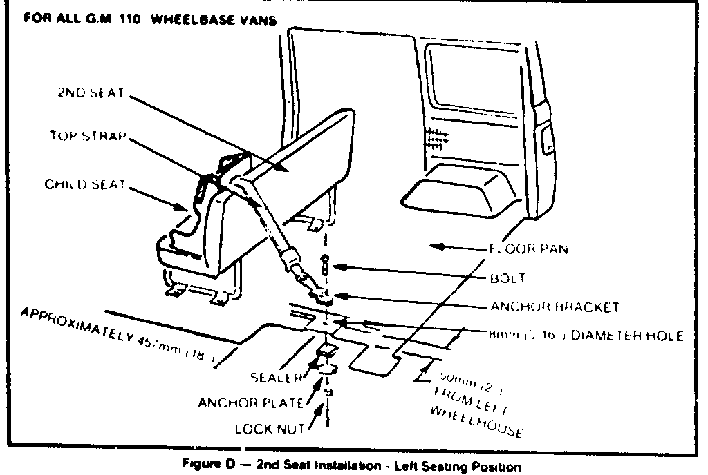
FOR ALL 110 INCH WHELLBASE "G" VANS FRONT PASBENGER SEAT INSTALLATION
A Child Seat is not recommmended for use in the front passenger seat of a 110 inch wheelbase van.
2ND SEAT INSTALLATION - VEHICLES NOT EQUIPPED WITH A 3RD SEAT
1. Left Seating Position - Drill an 8mm (5/16") diameter hole through the floor pan 50mm (2") inboard of the left wheelhouse and on the fore and aft center of the flat area of the floor pan located approximately 457mm (18") rearward of the front edge of the left wheelhouse. Refer to Figure D.
OR
Center Seating Position - Drill an 8mm (5/16") diameter hole through the floor pan 546mm (21 1/2") rearward of the front edge of the left wheelhouse and on the center of the depressed floor pan rib located 580mm inboard of the left wheelhouse. Refer to Figure E.
OR
Right Seating Position - Drill an 80mm (5/16") diameter hole through the floor pan 546mm (21 1/2") rearward of the front edge of the right wheelhouse and on the center of the depressed floor pan rib located 395mm (15-1/2") inboard of the right wheelhouse. Refer to Figure E.
2. To insure proper sealing of the hole, remove any dirt or foreign material from around the hole on the underside of the floor pan where the sealer is to be applied.
3. Place sealer on the hole from the underside of the floor pan and assemble the bolt, anchor bracket, anchor plate and lock nut to the floor pan as shown. Tighten securely and make certain that the hole is completely sealed.
4. Use the Child Seat only in the 2nd seat seating position for which the anchor bracket has been installed. Use the Child Seat as directed in the usage instructions, latching the Child Seat top strap hook to the anchor bracket as shown.
2nd SEAT INSTALLATION - FOR VEHICLES EQUIPPED WITH A 3RD SEAT
Use the Child Seat as directed in the usage instructions furnishad with the Child Seat, in any 2nd seat seating position. Latch the Child Seat top strap hook to the 3rd seat lap belt tongue located most directly behind the Child Seat.
3RD SEAT INSTALLATION
The Child Seat is not recommended for use in the 3rd seat of a 110 inch wheelbase "G" Van.
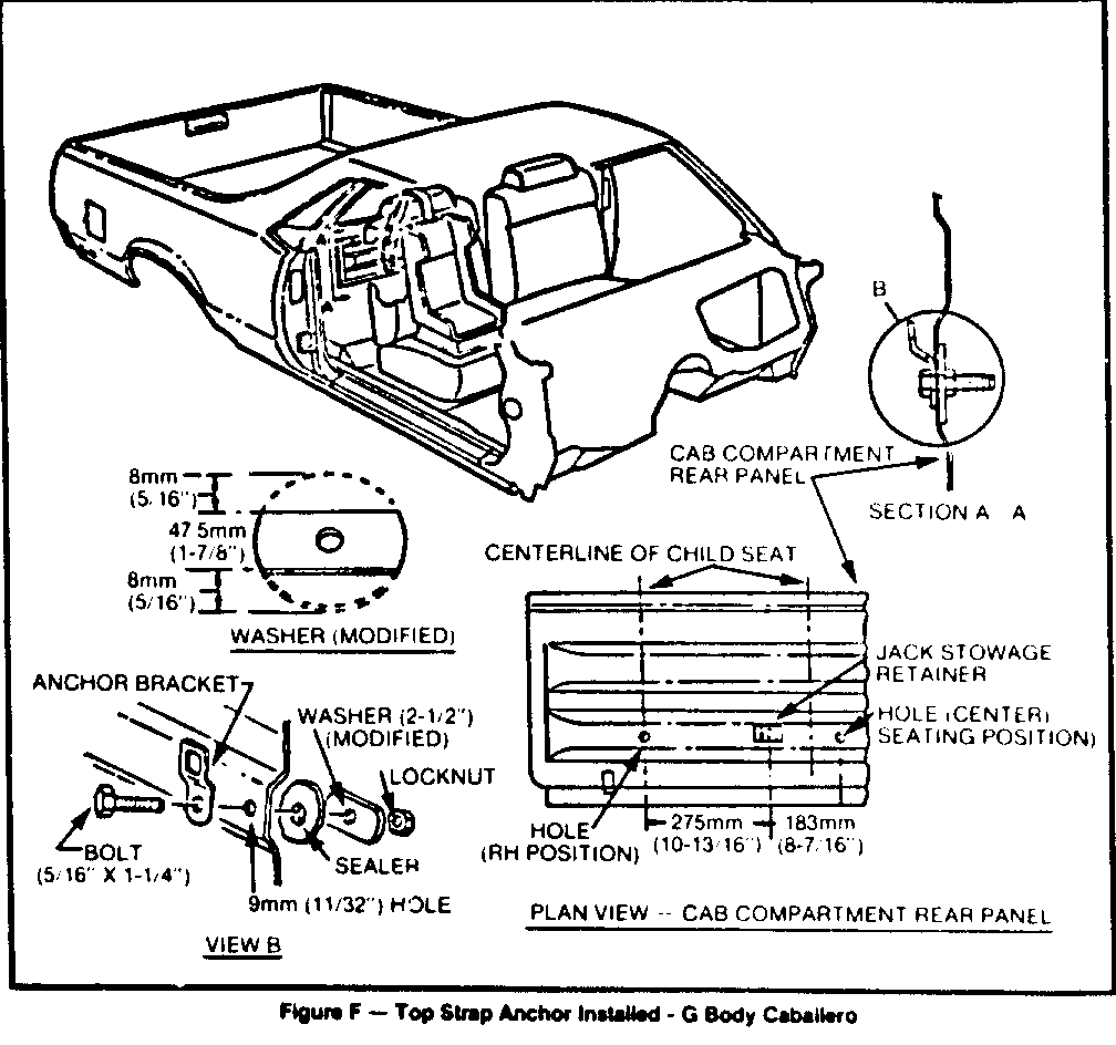
CABALLERO-Refer to Figure F
1. Remove trim cover from cab compartment rear panel.
2. Locate and drill the appropriate 9mm (11/32") hole in center of the compartment rear panel rib as shown in the plan view.
3. Modify the washer as shown.
S-T PICKUPS, EXTENDED CABS & JIMMY'S
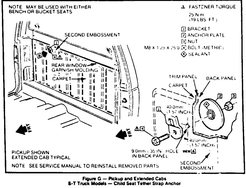
PICKUP AND EXTENDED CABS
1. Remove carpet and back panel trim panel as required to expose back panel sheet metal. Locate and provide hole in back panel. View A. CAUTION: to prevent damage to pickup box use drill stop.
2. After repositioning the carpet, pierce a hole in carpet and trim panel for bolt (4).
3. Sealer must be used as illustrated in View A.
NOTE: In the event the child seat anchorage assembly is removed, the 40mm (1.57") diameter hole must be properly resealed.
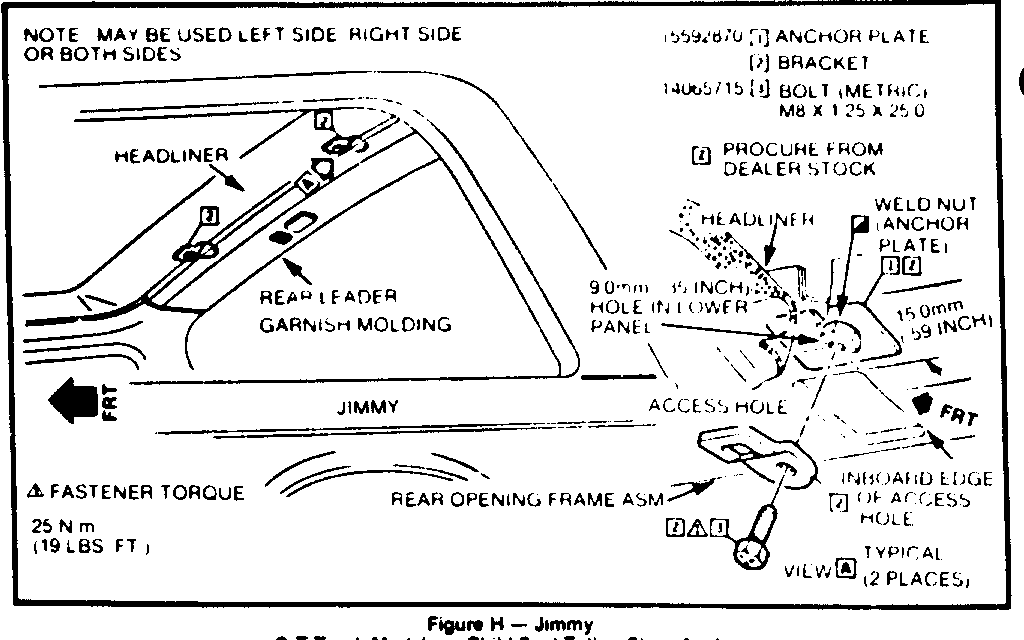
JIMMY'S
1. To expose access hole remove the rear header garnish molding and turn down the headliner. Locate hole in roof panel. View B. CAUTION: to prevent damage to the outer roof panel, use a drill stop.
2. Reposition the headliner and pierce for bolt (3). Align weld nut of anchor plate (1) with hole in headliner and inner sheet metal and install bracket (2) with bolt (3).
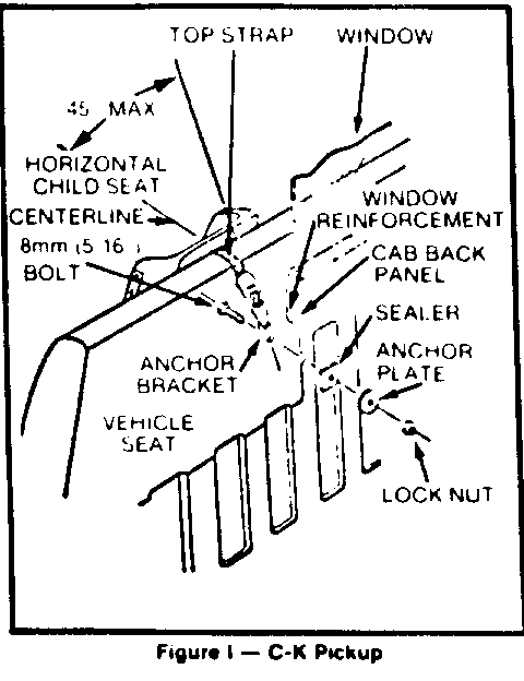
C-K PICKUP
Place the Child Seat in the front seating position (rear seating position on four door models) in which the Child Seat is to be used and secure the vehicle lap belt over the armrests of the Child Seat. This will correctly position the Child Seat for the anchor bracket installation.
Select a suitable anchor bracket mounting location on the cab back panel. (See Figure 1). The location must be:
A. Located near the rear window reinforcement. If a lower mounting position is desired, the angle between the Child Seat top strap and horizontal should not exceed 45 DEG.
B. As close to the centerline of the Child Seat as possible, but in no case more than 50mm (2 inches) outboard or 150mm (6 inches) inboard of the Child Seat centerline.
C. In a position clear of fuel tank, fuel lines, brake lines, exhaust systems, etc.
Drill an 8mm (5/16") diameter hole through the cab back panel of the selected location.
Assemble and securely tighten bolt, anchor bracket, anchor plate, 2 1/2" O.D. washer and lock nut to the cab back panel using a suitable sealer around the hole. Make certain that the hole is properly sealed to prevent exhaust fumes from entering the cab.
Use the Child Seat only in the seating position for which the anchor bracket has been installed, latching the Child Seat top strap hook to the anchor bracket as shown.
CAUTION:
In the event that the Child Seat anchorage assembly is removed, the 8mm (5/16") diameter hole must be properly resealed to prevent toxic exhaust fumes from entering the cab.
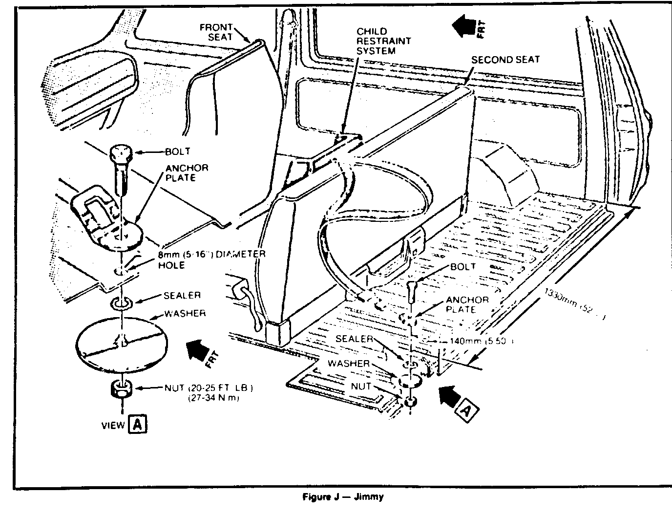
JIMMY
2ND SEAT INSTALLATION
1. Drill an 8mm (5/16") diameter hole through the floor pan 140mm (5.50") forward of the rear edge of the floor pan and on the center of the depressed floor pan rib (View A- Figure J).
A. Left Seating Position - 1,330mm (52.25")inboard of the right quarter inner panel. Refer to illustration.
2. To insure proper sealing of the hole, remove any dirt or foreign matter from around the hole on the underside of the floor pan where the sealer is to be applied.
3. Place sealer on the hole from the underside of the vehicle and assemble the bolt, anchor bracket, anchor plate, and lock nut to the floor pan as shown in View A. Tighten securely and make certain that the hole is completely sealed. Do not make the anchor installation without properly sealing the assembly.
4. Use the child seat only in the front seat-seating position for which the anchor bracket has been installed. Use the child seat as directed in your Child Seat Manufacturer's usage instructions, latching the child seat top strap hook to the anchor bracket.
NOTE: In the event the child seat anchorage assembly is removed, the 8mm (5/16") diameter hole must be properly resealed.
SUBURBAN
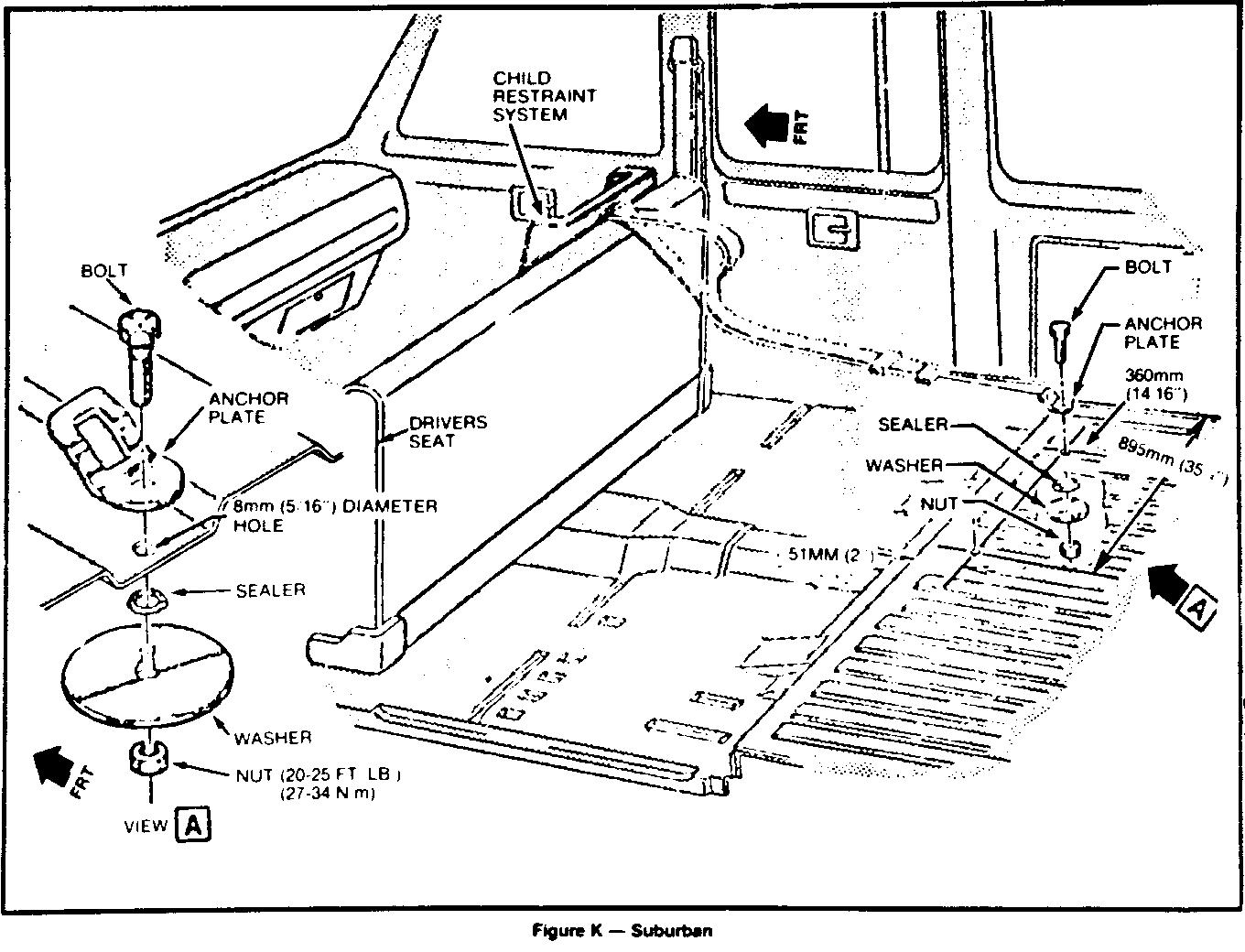
FRONT SEAT INSTALLATION - VEHICLES NOT EOUIPPED WITH A 2ND SEAT OR VEHICLES WITH THE 2ND SEAT IN THE DOWN POSITION
1. Drill a 8mm (5/16") diameter hole through the floor pan 51mm (2") rearward of the rear edge of the kick-up molding and on the center of the depressed floor pan rib (See View A, Figure K):
A. Right Seating Position - 360mm (14.6") inboard of the right quarter inner panel. Refer to Figure K.
B. Center Seating Position - 895mm (35.25") inboard of the right quarter inner panel. Refer to Figure K.
2. To insure proper sealing of the hole, remove any dirt or foreign matter from around the hold on the underside of the floor pan where the sealer is to be applied.
3. Place sealer on the hold from the underside of the vehicle and assemble the bolt, anchor bracket, anchor plate, and lock nut to the floor pan as shown in View A. Tighten securely and make certain that the hole is completely sealed. Do not make the anchor installation without properly sealing the assembly.
4. Use the child seat only in the front seat - seating position for which the anchor bracket has been installed. Use the child seat as directed in your Child Seat Manufacturer's usage instructions, latching the child seat top strap hook to the anchor bracket.
Note: In the event the child seat anchorage assembly is removed, the 8mm (5/16") inch diameter hole must be properly resealed.
SUBURBAN
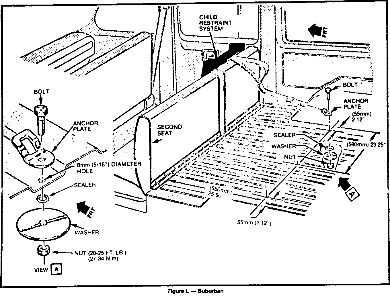
2ND SEAT INSTALLATION - VEHICLES NOT EQUIPPED WITH A 3RD SEAT
1. Drill a 8mm (5/16") diameter hole through the floor pan 650mm (25 1/2") rearward of the rear edge of the kick-up molding and:
A. Right Seating Position - 55mm (2.12') inboard of the right wheel house. Refer to Figure 1.
B. Center Seating Position - On the center of the depressed floor pan rib located 590mm (23.25") inboard of the right wheelhouse. Refer to Figure L.
C. Left Seating Position - 55mm (2.12") inboard of the left wheelhouse. Refer to Figure L.
2. To insure proper sealing of the hole, remove any dirt or foreign matter from around the hold on the underside of the floor pan where the sealer is to be applied.
3. Place sealer on the hole from the underside of the vehicle and assemble the bolt, anchor bracket, anchor plate and lock nut to the floor pan as shown in View A. Tighten securely and make certain that the hole is completely sealed. Do not make the anchor installation without properly sealing the assembly.
4. Use the child seat only in the 2nd seat-seating position for which the anchor bracket has been installed. Use the child seat as directed in your Child Seat Manufacturer's usage instructions, latching the child seat top strap hook to the anchor bracket.
Note: In the event the child seat anchorage assembly is removed, the 8mm (5/16") diameter hole must be properly resealed.
SUBURBAN
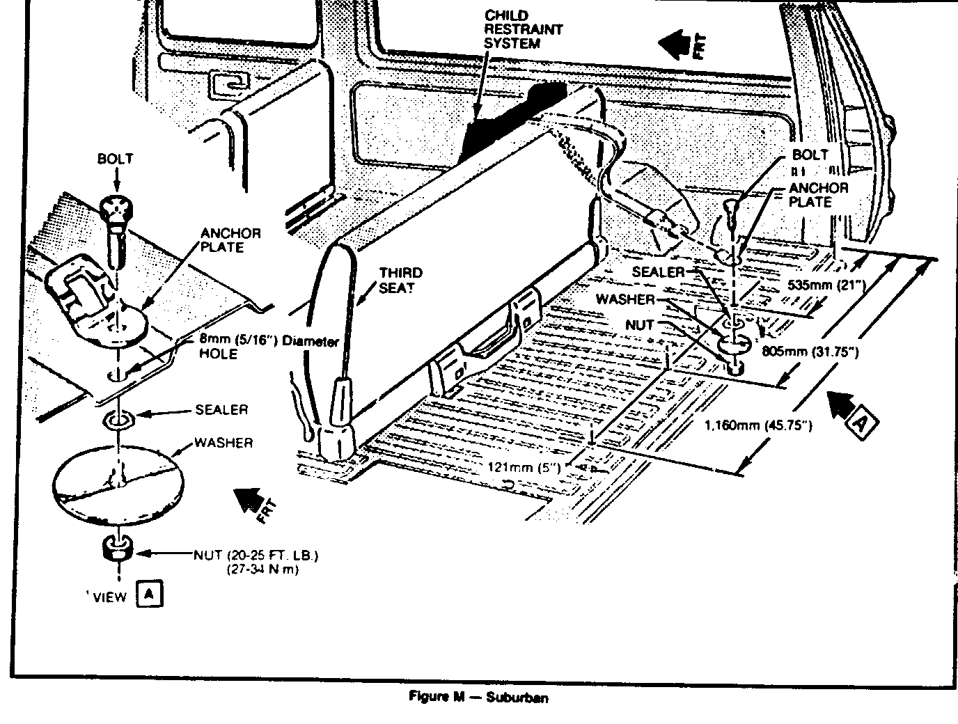
3RD SEAT INSTALLATION
1. Drill a 8mm (5/16") diameter hole through the floor pan 127mm (5") forward of the rear edge of the floor pan and on the center of the depressed floor pan rib (See View A):
A. Right Seating Position - 535mm (21:) inboard of the right quarter inner panel.
B. Center Seating Position - 805mm (31.75") inboard of the right quarter inner panel.
C. Left Seating Position - 1.160mm (45.75") inboard of the right quarter inner panel. Refer to Figure M.
2. To insure proper sealing of the hole, remove any dirt or foreign matter from around the hold on the underside of the floor pan where the sealer is to be applied.
3. Place sealer on the hole from the underside of the vehicle and assemble the bolt, anchor bracket, anchor plate, and lock nut to the floor pan as shown in View A. Tighten securely and make certain that the hole is completely sealed. Do not make the anchor installation without properly sealing the assembly.
4. Use the child seat only in the 3rd seat-seating position for which the anchor bracket has been installed. Use the child seat as directed in your Child Seat Manufacturer's usage instructions, latching the child seat top strap hook to the anchor bracket.
Note: In the event the child seat anchorage assembly is removed, the 8mm (5/16") diameter hole must be properly resealed.
Note: If the hole penetrates to the exterior of the vehicle, apply a sealant between the anchor bolt washer and the sheet metal to prevent carbon monoxide from entering the vehicle. Suitable sealers include silicone, butyl or acrylic type caulking.
In the event that the child seat anchorage assembly is removed, all bolt holes penetrating to the exterior of the vehicle must be resealed to prevent exhaust fumes from entering the vehicle.
General Motors bulletins are intended for use by professional technicians, not a "do-it-yourselfer". They are written to inform those technicians of conditions that may occur on some vehicles, or to provide information that could assist in the proper service of a vehicle. Properly trained technicians have the equipment, tools, safety instructions and know-how to do a job properly and safely. If a condition is described, do not assume that the bulletin applies to your vehicle, or that your vehicle will have that condition. See a General Motors dealer servicing your brand of General Motors vehicle for information on whether your vehicle may benefit from the information.
