Assembling The Differential Into the Axle
| • | J 8001 Dial Indicator Set |
| • | J 8092 Driver Handle |
| • | J 23690 Differential Side Bearing Installer |
| • | J 24385-C Differential Housing Spreader |
| • | J 39704 Master Differential Bearings |
- Force the ring gear to mesh with the pinion. Rock the ring gear in order to allow the gear teeth to mesh.
- Assemble the differential with the master bearings installed to the axle.
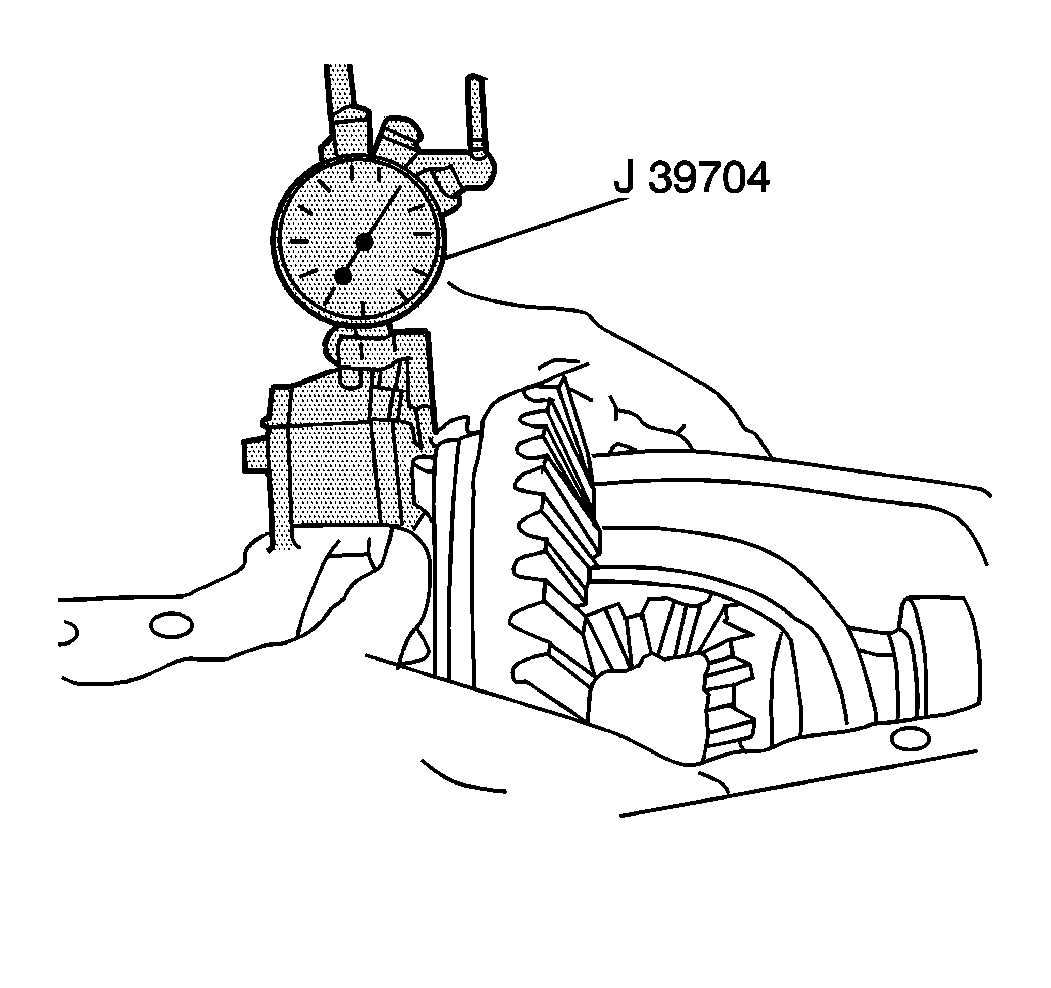
- Mount a J 8001 with a magnetic base on the ring gear bolt side of the housing.
- Place the indicator tip of the J 8001 on the chalk mark made earlier.
- With force still applied to the differential case, set the J 8001 to zero.
- Force the differential case away from the pinion gear in order to obtain a reading from the J 8001 .
- Repeat the last step until a consistent reading is obtained. Record the reading.
- Remove the J 8001 and the differential case from the axle housing.
- Remove the J 39705 from the differential case.
- Subtract the reading taken of the differential movement from the total shim pack size determined earlier. Refer to Determining Total Shim Pack Size .
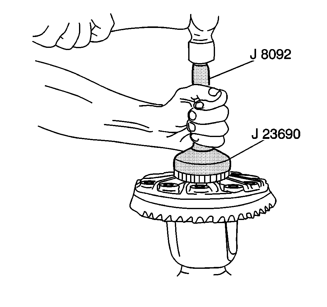
- Place the proper shims on the differential side of the bearing hub (ring gear side) and drive the differential bearing onto the hub using the J 8092 and J 23690 .
- Place the proper shims on the differential side of the bearing hub (opposite of the ring gear) and drive the differential bearing onto the hub using J 8092 and J 23690 .
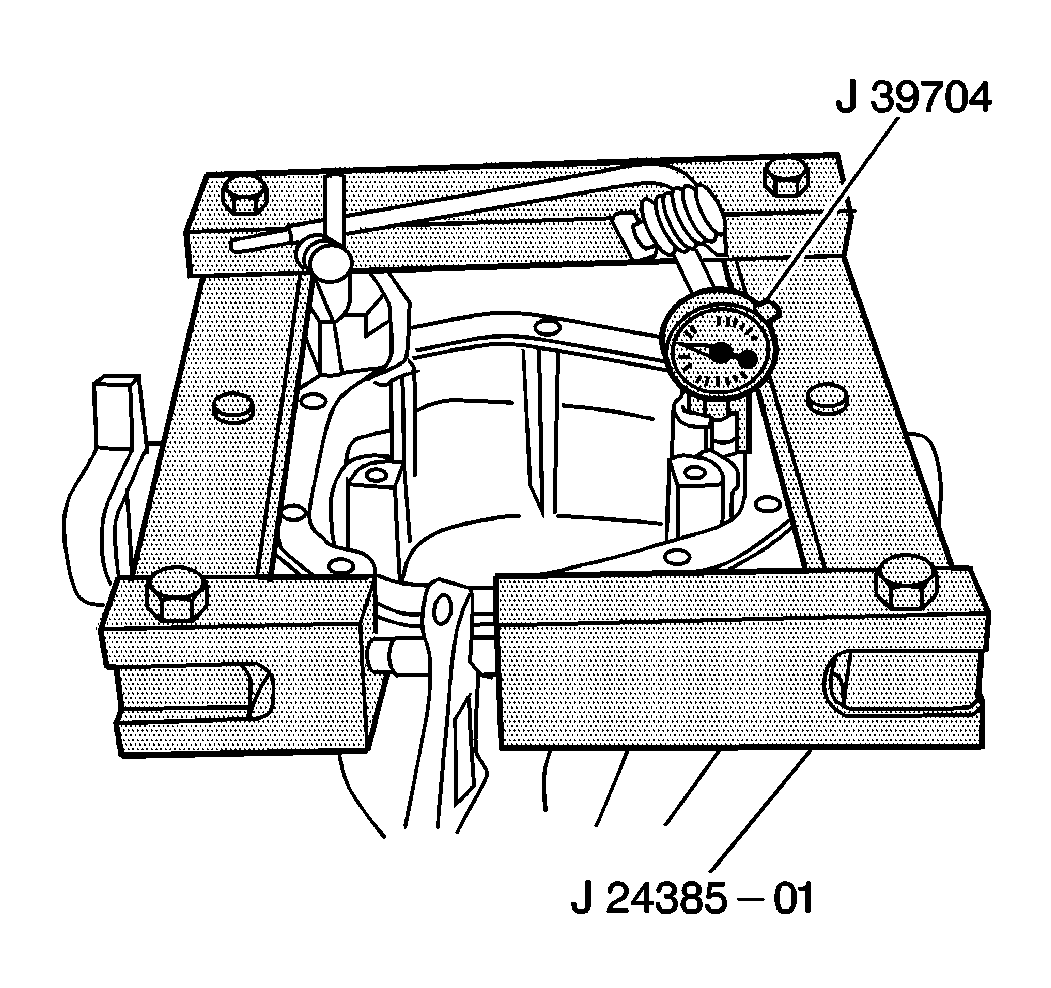
- Assemble the J 24385-C to the axle housing.
- Assemble the J 8001 .
- Preset the J 39704 to at least 0.05 mm (0.020 in).
- Rotate the indicator housing in order to zero the dial.
- Spread the housing while watching the J 8001 .
- Remove the J 8001 .
- Place the bearing cups onto the bearings.
- Install the differential assembly into the carrier.
- Seat the differential assembly into the axle using a soft-faced hammer.
- Remove the J 24385-C .
- Install the bearing caps.
- Install the bearing cap bolts.

Notice: If your axle assembly has selective outboard spacers and one 0.76 mm (0.030 inch) shim (each side) between the differential case and bearing cone. Make your measurements with the outboard spacers removed, but with the 0.76 mm (0.030 inch) shim assembled on the differential case trunion placed between the case and the master differential bearings. The selective outboard spacers are available in sizes (thickness) from 5.18 mm (0.2040 inch) to 6.10 mm (0.2400 inch), in 0.08 mm (0.003 inch) increments. The dial indicator should have the capability of making measurements up to 12.7 mm (0.500 inch).
Notice: If your axle assembly has outboard spacers, but controls the preload and backlash by using selective shims (each side) between the differential case and bearing cone. Make the measurements with the outboard spacers installed in the housing, but do not place any shims on the differential case hubs between the case and master differential bearings. The selective shims placed between the bearing cone and differential case are available in 0.08, 0.13, 0.25, 0.76 mm (0.003, 0.005, 0.010, 0.030 inch) sizes. The dial indicator should have the capability of making measurements up to 3.81 mm (0.150 inch).
Important: The pinion must be installed
| • | Use the reading taken of the differential movement for the shim size on the ring gear side. |
| • | Use the remainder from the equation in the last step for the shim size on the side opposite of the ring gear. |
| • | Add an additional 0.25 mm (0.010) in) of shims to the side opposite of the ring gear in order to preload the bearings. |

Important: If the axle assembly uses the outboard selective spacers, place the 0.76 mm (0.030 in) shim on the hub that was used along with the master bearings to make the measurement. Then select the appropriate outboard selective spacer and assemble the outboard selective spacer into the housing.
Important: If the axle assembly uses the outboard selective spacers, place the 0.76 mm (0.030 in) shim on the hub that was used along with the master bearings to make the measurement. Then select the appropriate outboard selective spacer and assemble the outboard selective spacer into the housing.

Notice: Do not spread the axle housing more than 0.38 mm (0.015 inch). Overspreading the housing may result in component damage.
Important: Install the bearing caps into the exact positions from which each had prior to removal.
Notice: Use the correct fastener in the correct location. Replacement fasteners must be the correct part number for that application. Fasteners requiring replacement or fasteners requiring the use of thread locking compound or sealant are identified in the service procedure. Do not use paints, lubricants, or corrosion inhibitors on fasteners or fastener joint surfaces unless specified. These coatings affect fastener torque and joint clamping force and may damage the fastener. Use the correct tightening sequence and specifications when installing fasteners in order to avoid damage to parts and systems.
Tighten
Tighten the bearing cap bolts to 115 N·m (85 lb ft).
