Pinion Flange Replacement 10 1/2 in. Ring Gear
Removal Procedure
Tools Required
| • | J 8614-01 Companion Flange Holder/Remover |
| • | J 24384 Pinion Oil Seal Installer |
The pinion oil seal and the pinion flange may be replaced with the carrier assembly installed in the vehicle.
- Raise the vehicle on a hoist and support with suitable safety stands.
- Remove the propeller shaft. Refer to Propeller Shaft Replacement or Two-Piece Propeller Shaft Replacement or Three-Piece Propeller Shaft Replacement in Propeller Shaft.
- Tie the propeller shaft to a frame rail or crossmember.
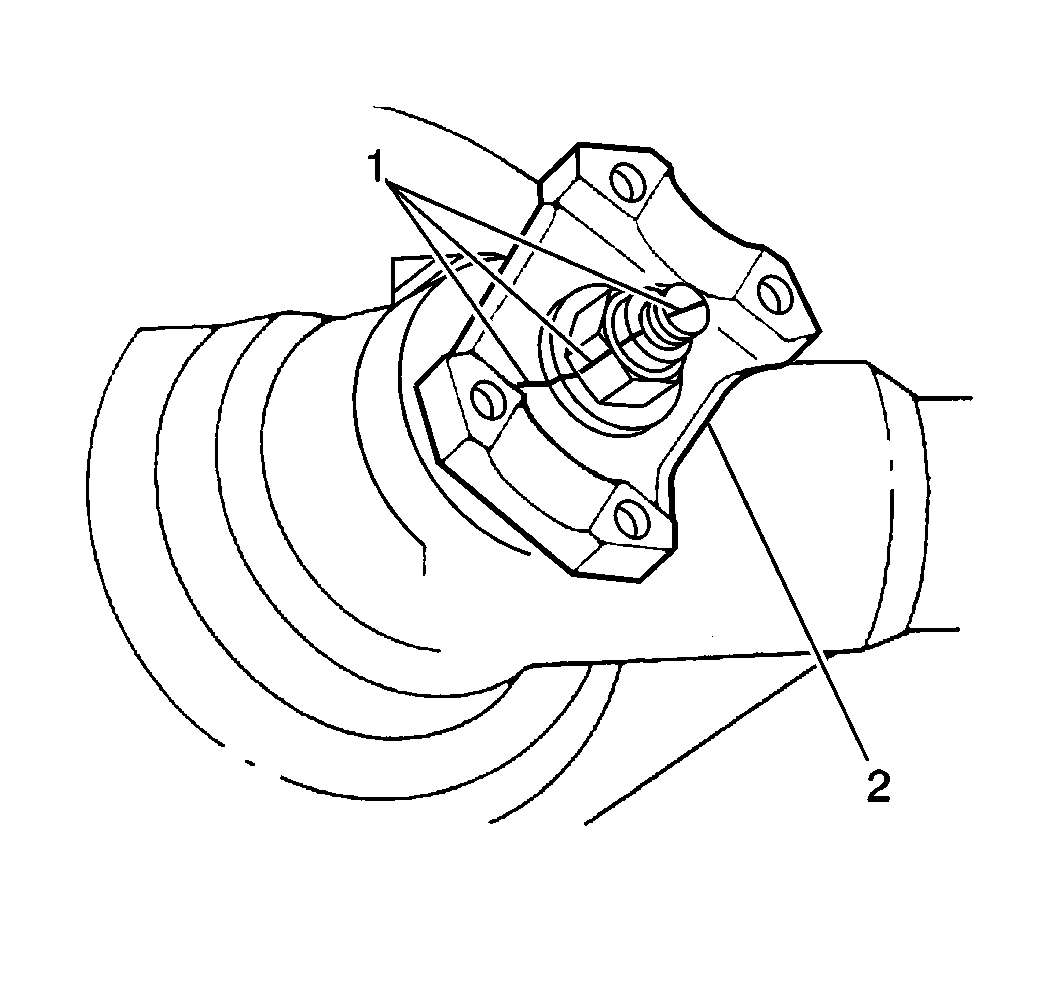
- Make an alignment mark (1) on the pinion shaft, pinion nut and companion flange (2). Use the mark as a guide during reinstallation.
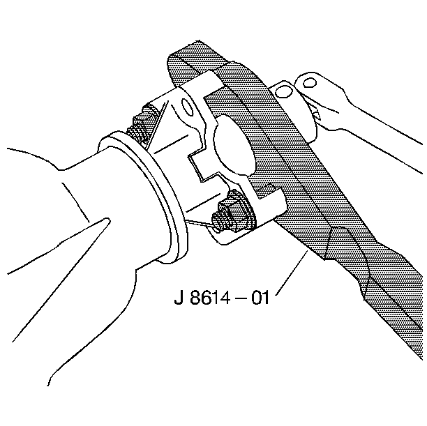
- Remove the nut using the J 8614-01 . Have a drain pan ready in order to catch the oil.
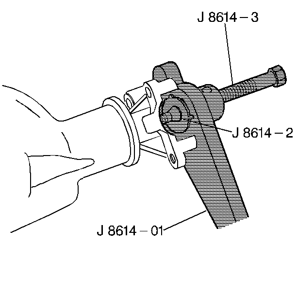
- Remove the flange using the J 8614-01 .
- Pry the oil seal from the bore.
- Thoroughly clean foreign material from the contact area.
- Replace parts as necessary.
Important: Do not damage the machined surfaces.
Installation Procedure
- Lubricate the cavity between the lips of the new seal with a high melting point bearing lubricant.
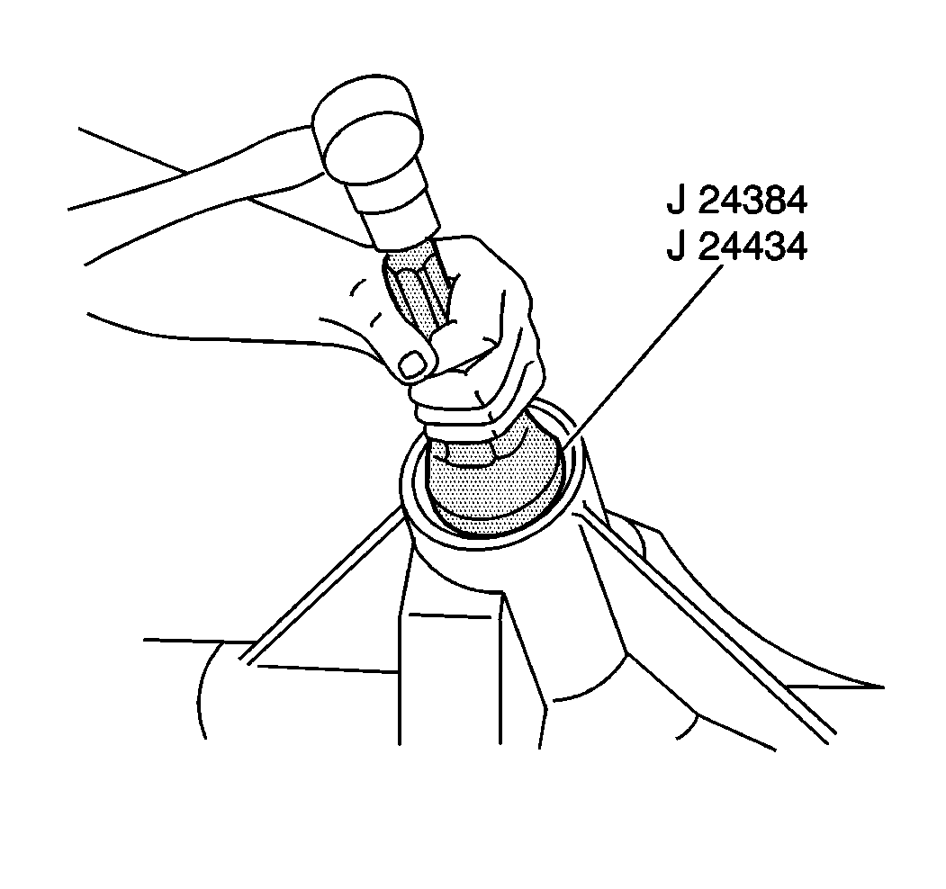
- Install the oil seal into the bore using the J 24384 .
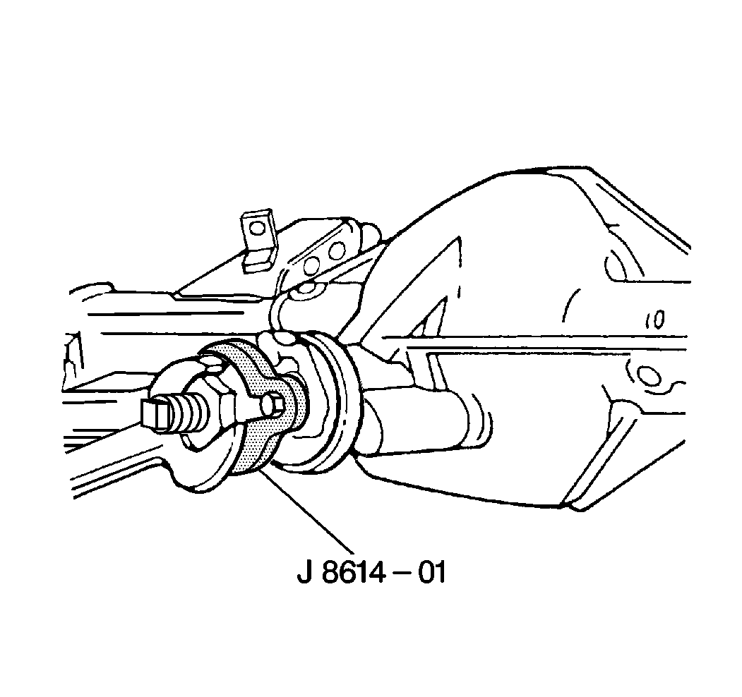
- Install the pinion flange using the J 8614-01 .
- Install the pinion nut using the J 8614-01 .
- Tighten the nut to the same position marked in the removal procedure.
- Tighten the pinion nut 1/16 inch beyond the alignment mark.
- Install the propeller shaft. Refer to Propeller Shaft Replacement or Two-Piece Propeller Shaft Replacement or Three-Piece Propeller Shaft Replacement in Propeller Shaft.
- Lower the vehicle.
Important: Use the alignment marks during reinstallation.
Notice: Use the correct fastener in the correct location. Replacement fasteners must be the correct part number for that application. Fasteners requiring replacement or fasteners requiring the use of thread locking compound or sealant are identified in the service procedure. Do not use paints, lubricants, or corrosion inhibitors on fasteners or fastener joint surfaces unless specified. These coatings affect fastener torque and joint clamping force and may damage the fastener. Use the correct tightening sequence and specifications when installing fasteners in order to avoid damage to parts and systems.
Tighten
Pinion Flange Replacement 11 in. Ring Gear
Removal Procedure
Tools Required
| • | J 8614-01 Pinion Flange Holder/Remover |
| • | J 24384 Pinion Oil Seal Installer |
The pinion oil seal and the pinion flange may be replaced with the carrier assembly installed in the vehicle.
- Raise the vehicle.
- Disconnect the propeller shaft. Refer to Propeller Shaft Replacement or Two-Piece Propeller Shaft Replacement or Three-Piece Propeller Shaft Replacement in Propeller Shaft.
- Make an alignment mark (1) on the pinion stem, pinion nut and pinion flange (2) for use as an installation guide.
- Remove the pinion nut using J 8614-01 .
- Remove the flange using J 8614-01 with the special nut and forcing screw.
- Pry the oil seal from the bore.
- Inspect the oil seal mating surfaces for any burrs which may cause seal failure.
- Inspect the flange deflector for any abnormality such as cracking or distortion.
- Replace parts as necessary.


| • | Do not damage the machined surfaces |
| • | Clean any foreign material from the contact area |
Installation Procedure
- Lubricate the inside diameter of the new oil seal with extreme pressure lubricant such as GM P/N 9985038.
- Install the oil seal into the bore using the J 24384 .
- Pack the cavity between the pinion stem, pinion flange and pinion nut with a non-hardening sealer such as Permatex® Type A or the equivalent.
- Install the pinion flange using the J 8614-01 . Use the alignment marks as a guide.
- Install the pinion nut using the J 8614-01 . Use the alignment marks as a guide.
- Install the propeller shaft. Refer to Propeller Shaft Replacement or Two-Piece Propeller Shaft Replacement or Three-Piece Propeller Shaft Replacement in Propeller Shaft.
- Lower the vehicle.
Important: Do not coat the bearing.

Notice: Use the correct fastener in the correct location. Replacement fasteners must be the correct part number for that application. Fasteners requiring replacement or fasteners requiring the use of thread locking compound or sealant are identified in the service procedure. Do not use paints, lubricants, or corrosion inhibitors on fasteners or fastener joint surfaces unless specified. These coatings affect fastener torque and joint clamping force and may damage the fastener. Use the correct tightening sequence and specifications when installing fasteners in order to avoid damage to parts and systems.
Tighten
Tighten the pinion nut to 597-678 N·m (440-550 lb ft).
