Removal Procedure
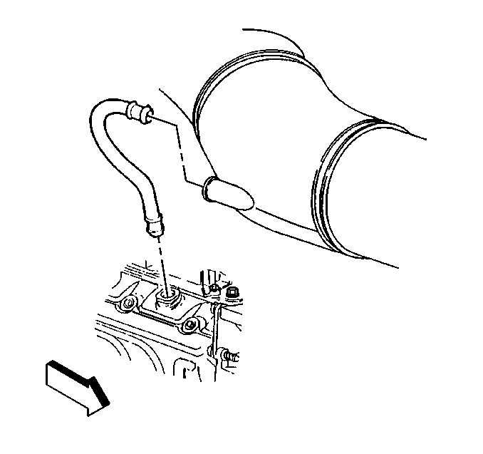
- Disconnect the crankcase vent tube from the rear intermediate duct.
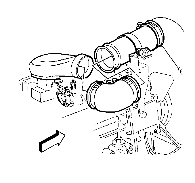
- Loosen the rear intermediate duct clamps and remove.
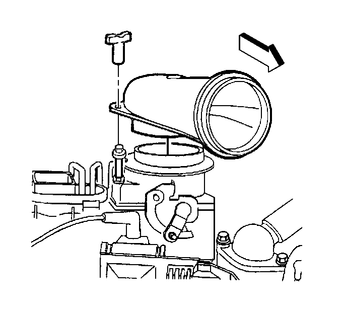
- Remove the air duct fastener and duct.
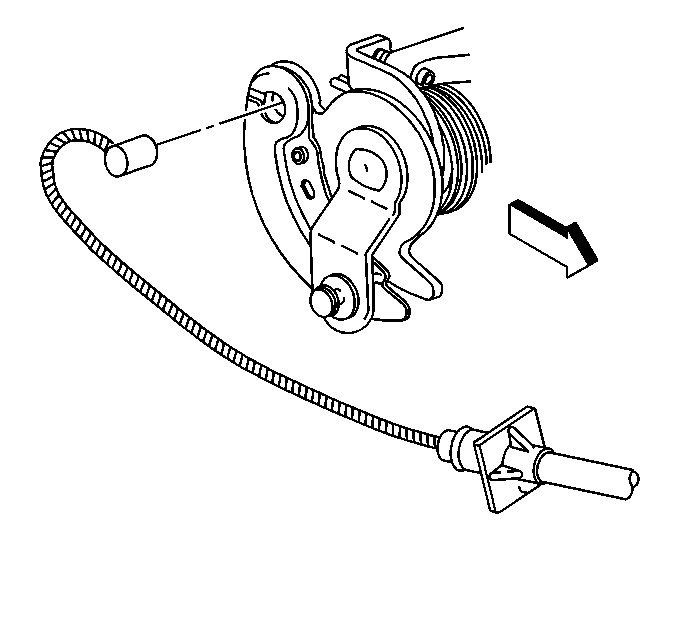
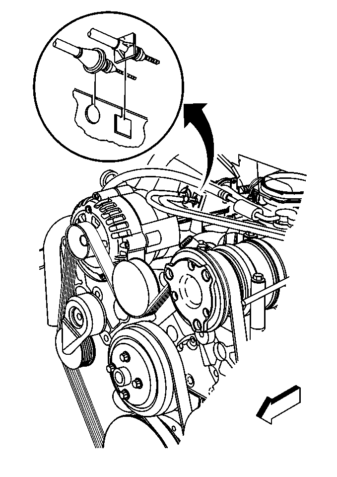
- Remove the accelerator cable from the from the throttle pulley.
- Remove the cable from the accelerator cable bracket by releasing the accelerator cable retainer locking tangs.
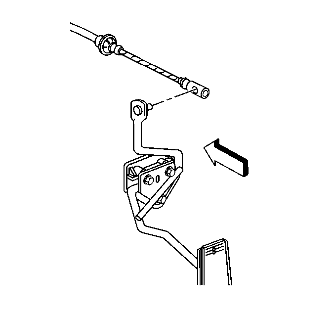
- Remove the accelerator cable end from the accelerator pedal lever.
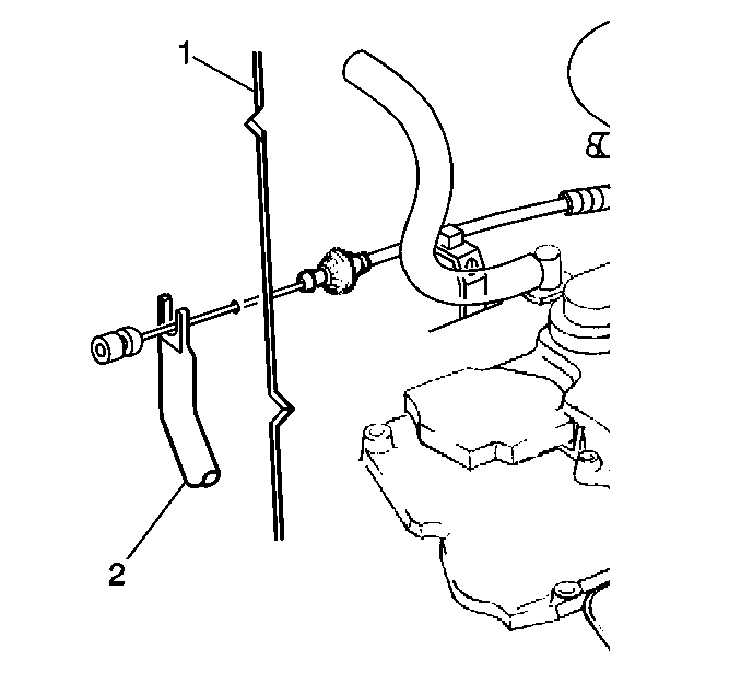
- Remove the accelerator cable from the dash panel.
Installation Procedure
Important: Observe the following when installing the accelerator cable in order
to insure the proper operation of the accelerator controls:
• Replace the accelerator cable with an identical replacement part. • Do not route the accelerator cable within 13 mm (0.52 in)
at any point of travel of wires, cables, hoses or other flexible components. • The accelerator controls operate without binding between closed
throttle and wide open throttle position.
- Insert the accelerator cable through the dash panel until the locking tangs are fully seated and locked into position.
- Install the accelerator cable to the accelerator pedal lever.
- Insert the accelerator cable through the accelerator cable support until the locking tangs are fully seated and locked into position.
- Insert the accelerator cable into the throttle pulley slot and groove.
- Install the air inlet duct and fastener.
- Install the rear intermediate duct.
- Install the crankcase vent tube to the rear intermediate duct.
- With the ignition OFF, check the pedal for full range of movement.


Important: Do not twist or kink the accelerator cable in order to insure the cable is properly seated in the throttle pulley groove.

Notice: Use the correct fastener in the correct location. Replacement fasteners must be the correct part number for that application. Fasteners requiring replacement or fasteners requiring the use of thread locking compound or sealant are identified in the service procedure. Do not use paints, lubricants, or corrosion inhibitors on fasteners or fastener joint surfaces unless specified. These coatings affect fastener torque and joint clamping force and may damage the fastener. Use the correct tightening sequence and specifications when installing fasteners in order to avoid damage to parts and systems.
Tighten
Tighten the fastener to 2.5N·m (22 lb. in.)


Important: The pedal must operate freely without binding through the full range of pedal movement.
