IDLE SPEEDS HIGHER THAN DESIRE INCORRECTLY WIRED SOLENOID

MODELS: 1982 15, 25 AND 35 SERIES "G" VANS WITH LE3 (4.1L L6) WITH C60 AND NA5
In the event of a comment of a slightly high idle speed (650 rpm), the following steps should be taken to insure that the carburetor mounted idle stop solenoid was wired correctly.
1. With the ignition key and the A/C control switch in the off position, make sure the idle stop solenoid plunger is retracted and not contacting the throttle lever.
2. Turn on the ignition key, the plunger should not have moved until the air conditioning is turned on.
3. If the idle stop solenoid plunger extends with the ignition key on and the air conditioning off, it will be necessary to correct the wiring to the solenoid.
4. Design intent is to increase the idle speed, approximately 100 rpm, only upon air conditioning demand. Reference Service Manual, Sections 1B19 C60 System Wiring Diagram and 6C2-4 procedure for checking idle stop solenoid.
If it is found that the solenoid has been wired incorrectly, the following procedure and components are required to correct the condition.
Part Qty. Number Part Name
1 NPN 40.0 inches of 18 ga. wire 1 8911256 Connector - wire end 1 6288704 Connector - wire end 2 3816659 Strap - wire tie
The following steps should be followed to install the components previously listed:
1. Unplug the existing wire from the idle stop solenoid. Double the lead back and tape it to the harness. The plug end is to be taped and well insulated to avoid shorting on adjacent components.
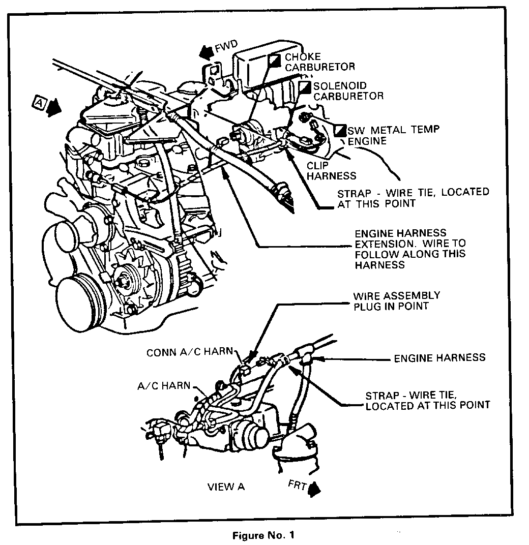
2. Install new idle stop solenoid wire. One end connects to the solenoid, the other to the open plug at the air conditioning compressor clutch "pigtail".
3. The idle stop solenoid wire should follow along and be attached to the engine wiring harness using two (2) straps.
4. One (1) strap is to be located at the metal clip (part of engine wiring harness assemby) which is attached to the body 3.5 inches to the right of vehicle center line.
5. The second strap is to be located just forward of the plastic harness retainer (part of the engine wiring harness). The plastic retainer is to the rear of the choke housing and forward of the idle stop solenoid.
6. See attached sketch as to wire routing and strap locations.
7. Upon completion of the wiring change, idle speed should be checked with the idle stop solenoid both active and inactive. Reference: Service Manual, Section 6C2, page 5.

General Motors bulletins are intended for use by professional technicians, not a "do-it-yourselfer". They are written to inform those technicians of conditions that may occur on some vehicles, or to provide information that could assist in the proper service of a vehicle. Properly trained technicians have the equipment, tools, safety instructions and know-how to do a job properly and safely. If a condition is described, do not assume that the bulletin applies to your vehicle, or that your vehicle will have that condition. See a General Motors dealer servicing your brand of General Motors vehicle for information on whether your vehicle may benefit from the information.
