Charging System Check Battery Testing
Tools Required
J 42000 Digital Battery Tester
Perform the following procedures in order to test batteries:
Visual Inspection Procedure
- Inspect for obvious damage that may permit the loss of electrolyte.
- Determine the cause of the damage.
- Correct the damage as necessary.
A cracked or broken battery case is an example of the above damage.
If no obvious damage exists, proceed to the Hydrometer Inspection.
Hydrometer Inspection
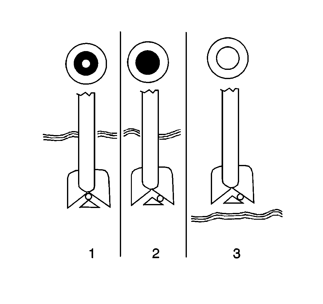
- Inspect for green dot visibility (1).
- Inspect for Darkness (2). (The green dot is not visible.)
- Inspect for a clear or yellow color (3).

If the green dot is visible (1), the battery state of charge is 65 percent or more. The battery is ready for testing. Proceed to Battery Load Testing.
If the hydrometer is dark (2), charge the battery. Refer to Battery Charge Low or Completely Discharged . Proceed to Battery Load Testing.
If a clear or yellow color exists (3), replace the battery.
Battery Load Testing
- Use battery terminal adapters in order to ensure a proper connection during battery load testing.
- Inspect the battery in order to ensure that the battery is not frozen.
- Turn all of the electrical loads off.
- Use the J 42000 in order to measure the voltage across the battery terminals.
- With the J 42000 attached, connect a battery load tester across the battery terminals.
- Apply a 300 ampere load for 15 seconds to the battery in order to remove the surface charge from the battery.
- Wait 15 seconds in order to allow the battery to recover.
- Apply the specified amperage load to the battery. The battery specification label determines the appropriate voltage.
- Load the battery for 15 seconds. Read the voltage and remove the load.
- If the voltage remains above the minimum value, the battery is good and should be returned to service. Refer to Battery Temperature and Minimum Voltage in General Specifications . Estimate the battery temperature by feel, and the temperature that the battery has been exposed to for the preceding few hours.
- Replace the battery if the voltage drops below the listed minimum value.

If the battery is frozen do not load test the battery. Replace the battery.
When the green dot appears in the hydrometer, the voltage should equal or exceed 12 volts. Replace the battery if the voltage is less than 12 volts, unless the battery has just been discharged (such as by load testing or cranking the engine).
Important: Do not perform this step if the battery has not been recently charged.
Charging System Check 21-SI 200 Generator
Using the Digital Multimeter
Tools Required
| • | J 39200 Digital Multimeter |
| • | J 35590 Inductive Current Clamp |
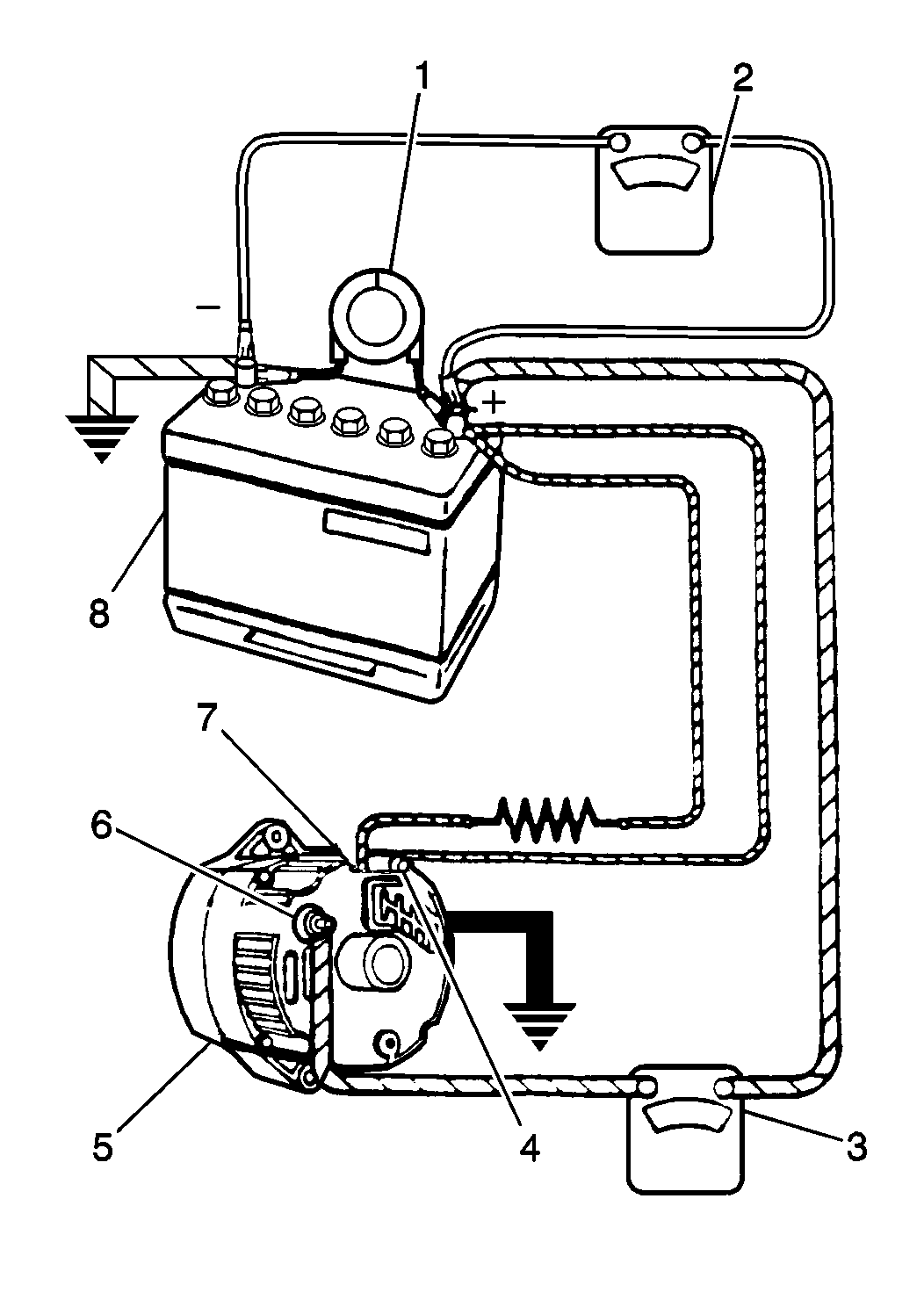
- Disconnect the negative battery cable. Refer to Negative Battery Cable in Battery Cable Replacement .
- Connect an ammeter in series between the BAT terminal of the generator and the output lead.
- Connect the negative battery cable. Refer to Negative Battery Cable in Battery Cable Replacement .
- Start the engine.
- Turn ON the following components:
- Connect a carbon pile across the battery.
- Operate the engine at 2500 RPM.
- Adjust the carbon pile as necessary in order to obtain the maximum current output.
- If the ampere output is within 10 amperes of the rated output stamped on the generator frame, the generator functions properly.
- If the ampere output is not within 10 amperes of the rated output stamped on the generator frame, repair the generator. Refer to Generator Overhaul
Caution: Unless directed otherwise, the ignition and start switch must be in the OFF or LOCK position, and all electrical loads must be OFF before servicing any electrical component. Disconnect the negative battery cable to prevent an electrical spark should a tool or equipment come in contact with an exposed electrical terminal. Failure to follow these precautions may result in personal injury and/or damage to the vehicle or its components.
| • | The radio |
| • | The windshield wipers |
| • | The headlamps (high beam) |
| • | The blower motor (high speed) |

Important: Residual magnetism in the rotor causes the initial voltage buildup. Increase the engine speed as necessary in order to obtain the maximum current output.
Using the Inductive Current Clamp
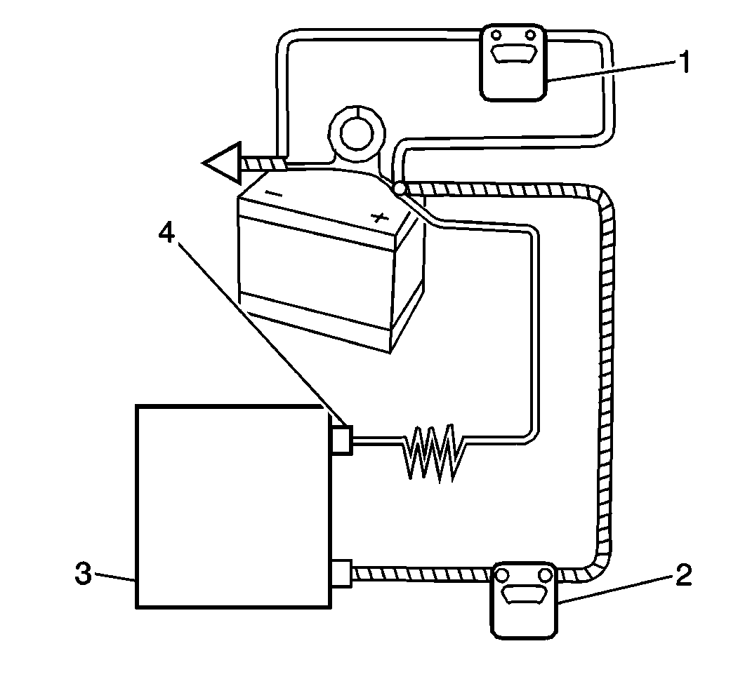
- Install the J 35590 .
- Start the engine.
- Turn ON the following components:
- Connect a carbon pile across the battery.
- Operate the engine at 2500 RPM.
- Adjust the carbon pile as necessary in order to obtain the maximum current output.
- If the ampere output is within 10 amperes of the rated output stamped on the generator frame, the generator functions properly.
- If the ampere output is not within 10 amperes of the rated output stamped on the generator frame, repair the generator. Refer to Generator Overhaul .
| • | The radio |
| • | The windshield wipers |
| • | The headlamps (high beam) |
| • | The blower motor (high speed) |

Important: Residual magnetism in the rotor causes the initial voltage buildup. Increase the engine speed as necessary in order to obtain the maximum current output.
Charging System Check CS-144 Generator
Tools Required
| • | J 39200 Digital Multimeter |
| • | J 35590 Inductive Current Clamp |
- Disconnect the wire harness from the generator.
- Set the J 39200 to the DC voltage scale.
- Connect the J 39200 from ground to the L terminal in the wiring harness.
- Verify that the voltage is B+.
- Correct any faults as necessary.
- Connect the electrical connector to the generator.
- Turn OFF all of the accessories.
- Run the engine at 2500 RPM.
- Measure the voltage across the battery.
- Disconnect the negative battery cable. Refer to Negative Battery Cable in Battery Cable Replacement .
- If you use the J 39200 , connect an ammeter in series between the BAT terminal of the generator and the output lead. Ensure that the ammeter is able to measure 115 amps of current.
- If you use the J 35590 , install the J 35590 around the generator output lead.
- Connect the negative battery cable. Refer to Negative Battery Cable in Battery Cable Replacement .
- Connect a carbon pile across the battery.
- Start the engine.
- Run the engine at 2500 RPM.
- Turn ON the accessories.
- Load the battery using a carbon pile in order to obtain maximum amperage.
- Maintain the voltage at 13 volts or above.
- If the output is within 15 amperes of the rated output, the generator is working properly.
- If the output is not within 15 amperes of the rated output, replace the generator.
A reading other than B+ indicates one of the following faults between the terminal and the battery:
| • | An open circuit |
| • | A high resistance |
| • | A grounded circuit |
If the voltage is above 16 volts, replace the generator.
Caution: Unless directed otherwise, the ignition and start switch must be in the OFF or LOCK position, and all electrical loads must be OFF before servicing any electrical component. Disconnect the negative battery cable to prevent an electrical spark should a tool or equipment come in contact with an exposed electrical terminal. Failure to follow these precautions may result in personal injury and/or damage to the vehicle or its components.

