Removal Procedure
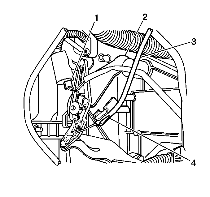
- Remove the mode control
cable (3) at the heater case.
- Disconnect the defroster switch (1), if equipped.
- Remove the 2 screws and the defroster switch as necessary.

- Remove the temperature
control cable (1) at the heater case.
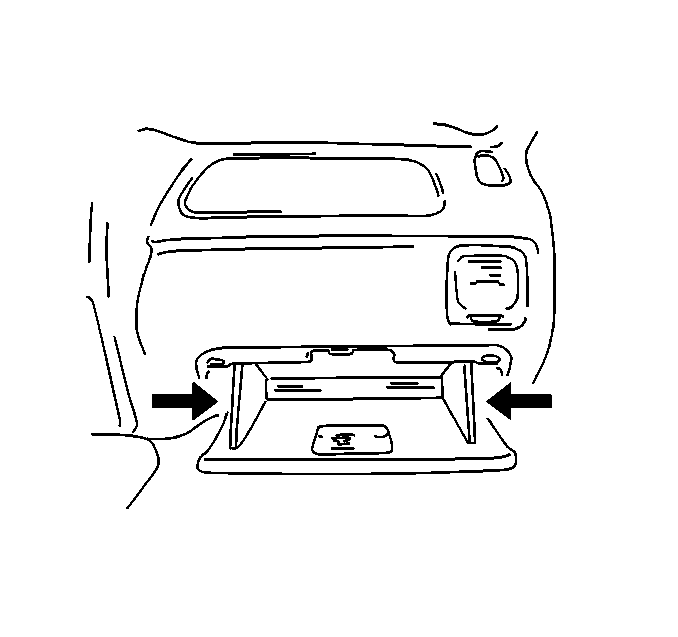
- Open the instrument panel
(IP) compartment.
- Push in the left and right side of the IP compartment and lower
the IP compartment.
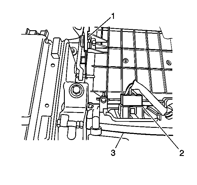
- Remove the fresh/recirc
control cable (1) at the blower case.
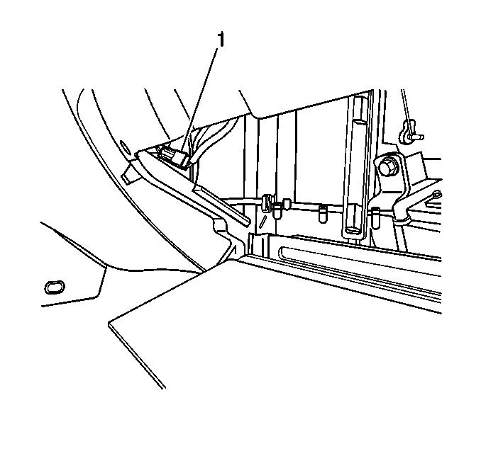
- Disconnect the A/C switch
connector (1), if equipped.
- Remove the IP cluster trim bezel. Refer to
Instrument Panel Cluster Trim Plate Bezel Replacement
in Instrument Panel,
Gages and Console.
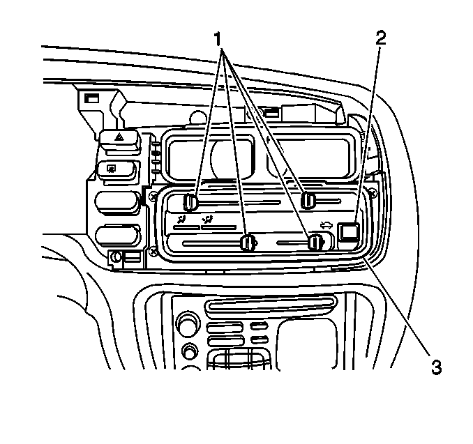
- Pull the knobs (1)
from the levers.
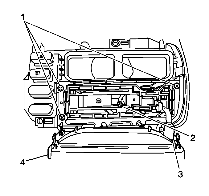
- Gently pry the heater
control fascia (4) from the control assembly.
- Twist and remove the bulb socket (2).
- Remove the 3 screws (1).
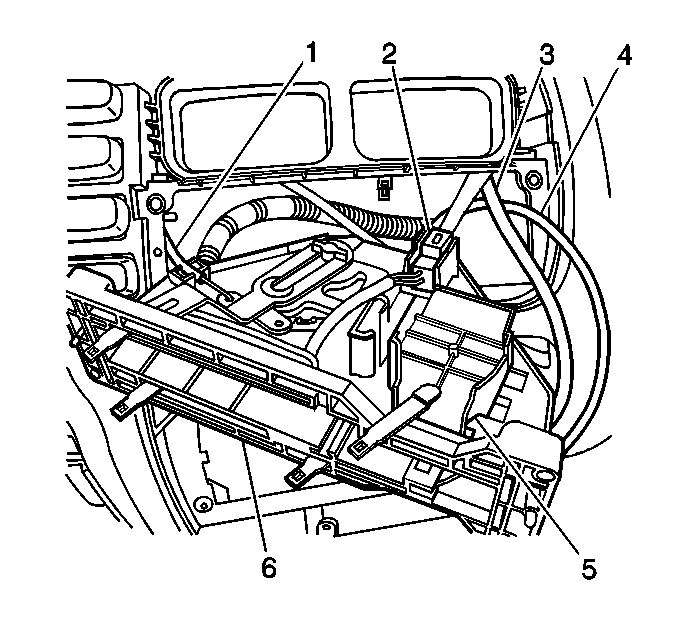
- Tilt the heater control
unit to one side and pull through the IP.
- Disconnect the blower switch electrical connector (5).
Important: Note the routing position of the cables in order to facilitate installation.
- Remove the heater control unit from the IP with the cables attached.
- Remove the blower switch from the heater control unit, as necessary.
- Remove the A/C switch from the heater control unit, as necessary.
- Disconnect each control cable from the heater control unit:
| 19.1. | Gently pry the temperature control cable (4) sheath from
the heater control unit. Unhook the cable from the lever arm. |
| 19.2. | Gently pry the mode control cable (1) sheath from the heater
control unit. Unhook the cable from the lever arm. |
| 19.3. | Gently pry the fresh/recirc control cable (3) from the
heater control unit. Unhook the cable from the lever arm. |
Installation Procedure
- Connect each control cable to the heater control unit by performing
the following:
| 1.1. | Hook the end of the cable into the hole in the lever arm. |
| 1.2. | Slide the sheath back on the cable. |
| 1.3. | Line up the sheath with the sheath retainer. |
| 1.4. | Slide the sheath into its retainer until it snaps into place. |

- Install the A/C switch
to the heater control unit, as necessary.
- Install the blower switch to the heater control unit, as necessary.
- Position the cables and tilt the heater control unit to one side
and install to the IP.
- Connect the blower switch electrical connector (5).

- Install the bulb socket (2).
- Install the heater control fascia (4) to the control assembly.
- Install the 3 screws (1).

- Install the knobs (1)
to the levers.
- Install the IP cluster trim bezel. Refer to
Instrument Panel Cluster Trim Plate Bezel Replacement
in Instrument Panel,
Gages and Console.

- Connect the A/C switch
connector (1), if equipped.

- Install the fresh/recirc
control cable (1) onto the pin of the fresh/recirc door and install
the cable to the clip at the heater case.
- Close the IP compartment.

- Install the temperature
control cable (1) at the heater case.

- Install the mode control
cable (3) at the heater case.
- Connect the defroster switch (1), if equipped.
- Install the defroster switch, if removed. Secure with the 2 screws.
- Adjust the control cables as necessary. Refer to the following:


