Harsh Clunk Noise from Front Axle While in 4WD and During Turning Maneuvers (Replace Front Differential Case, Actuator and Side Bearings)

| Subject: | Harsh Clunk Noise From Front Axle While in 4WD and During Turning Maneuvers (Replace Front Differential Case, Actuator and Side Bearings) |
| Models: | 1999 Chevrolet Tracker |
| with Four-Wheel Drive |
Condition
Some customers may comment on a harsh clunk or popping noise coming from the front axle. This condition is most apparent while driving in 4 WD at low speeds on loose traction surfaces such as gravel or snow and turning right of left.
Cause
Inside the front differential case, the teeth of the free wheel axle hub may jump a tooth resulting in the noise.
Correction
A modification was made to the design of the front differential case, which should reduce the likelihood of the free wheel hub teeth from jumping.
Replace the front axle differential case, actuator and side bearings using the service procedure and part numbers listed in this bulletin.
Important: With the new design differential case, the teeth may still jump under extreme torque load conditions, such as making tight turn maneuvers in 4 WD on hard dry surfaces resulting in a similar noise. This noise is now considered to be a normal vehicle operating characteristic. Driving on high traction surfaces in 4 WD is not necessary and contributes to excessive torque load on the front axle. Customers should be advised to shift into 2 WD when driving on such surfaces.
Tools Required
| • | J 24319-B Universal Steering Linkage Puller |
| • | J 37780 Axle Shaft Remover |
| • | J 3289-21 Holding Fixture |
| • | J 37769 Differential Holding Fixture Adapters |
| • | J 3289-20 Holding Fixture Base |
| • | J 22888-D Side Bearing Remover |
| • | J 8107-4 Differential Side Bearing Remover Plug |
| • | J 37758 Pinion Outer Race Installer |
| • | J 8092 Driver Handle |
| • | J 24433 Side Bearing Installer |
- Raise and suitably support the vehicle. Refer to the General Information sub-section in the Service Manual.
- Remove the 4 bolts and the front skid plate from the vehicle, if equipped.
- Place a drain pan or suitable container under the front axle assembly.
- Remove the front axle housing drain plug (2) and drain the front axle oil.
- Remove the right front wheel.
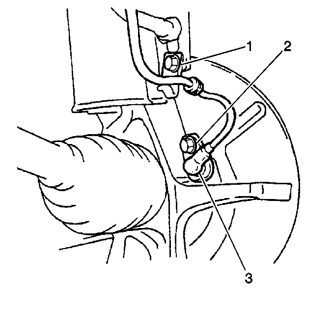
- Disconnect the right side front wheel speed sensor electrical connector.
- Remove the right side front wheel speed sensor retaining bolt (2) and sensor (3) from the steering knuckle.
- Remove the right outer tie rod lock nut.
- Separate the right outer tie rod from the steering knuckle using the J 24319-B.
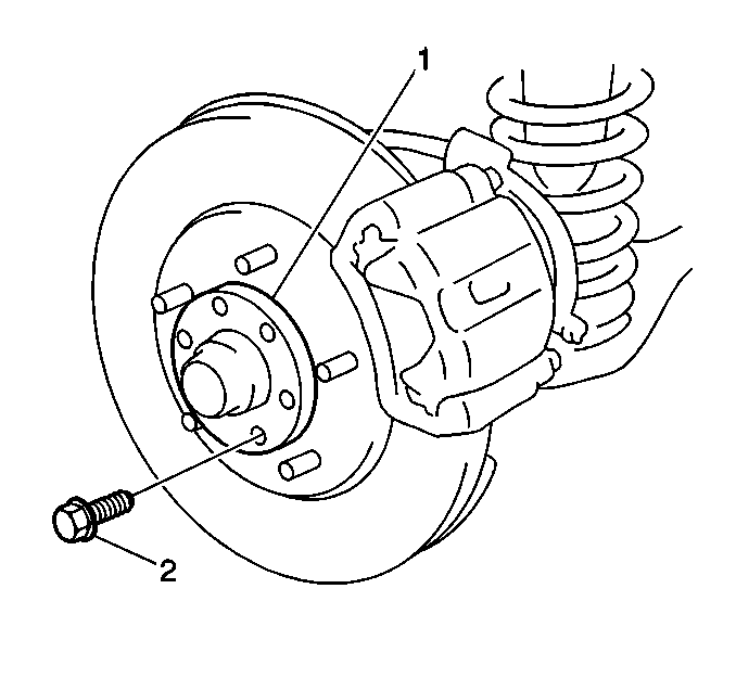
- Remove the 6 bolts (2) and the flange (1).
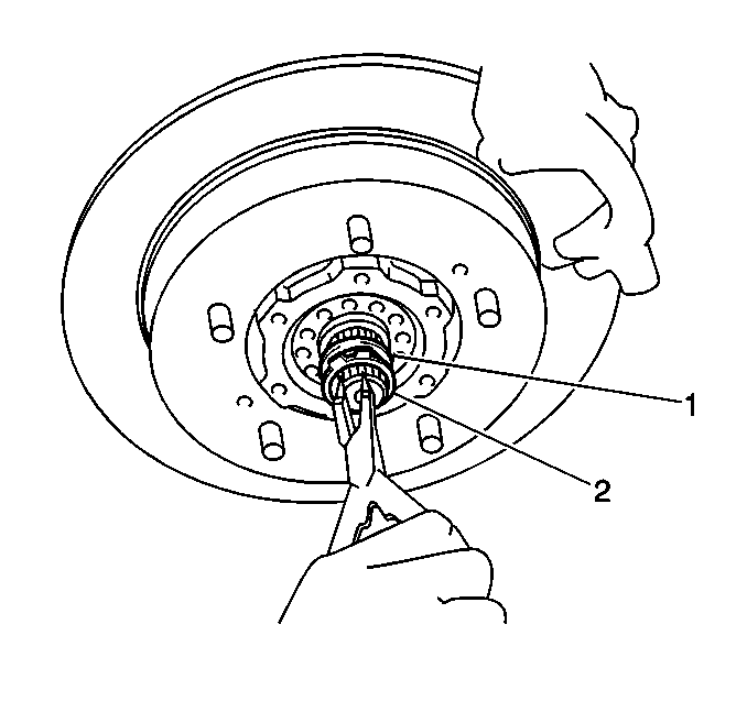
- Remove the drive axle shaft snap ring (2).
- Remove the drive axle shaft spindle washer (1) from the drive axle shaft.
- Remove the caliper bolts and caliper from mounting bracket and set aside.
- Remove the right and left stabilizer shaft link nuts (1). Remove stabilizer shaft and bushings from the control arms.
- Use a hydraulic jack in order to support the right control arm.
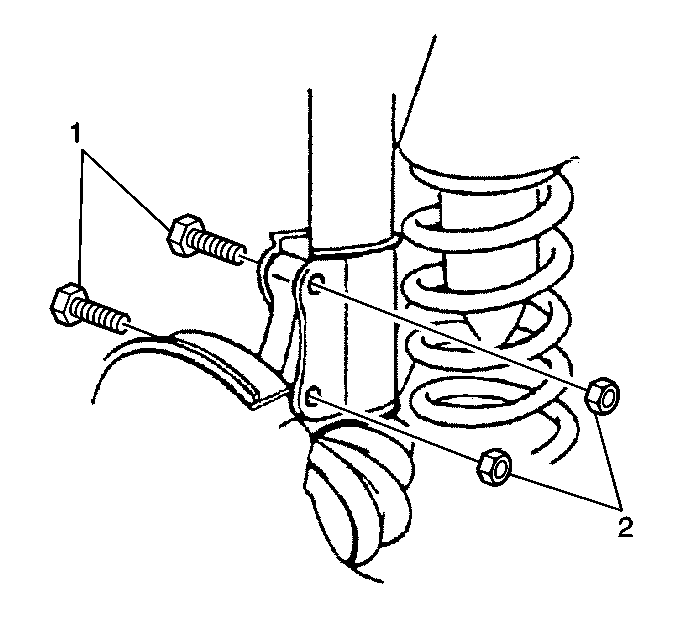
- Remove the right strut bracket to steering knuckle bolts (1) and nuts (2).
- Remove the right ball joint lock nut.
- Use the J 24319-B in order to separate the lower control ball joint from the knuckle.
- Remove the right steering knuckle/hub assembly.
- While lowering the hydraulic jack, remove the coil spring.
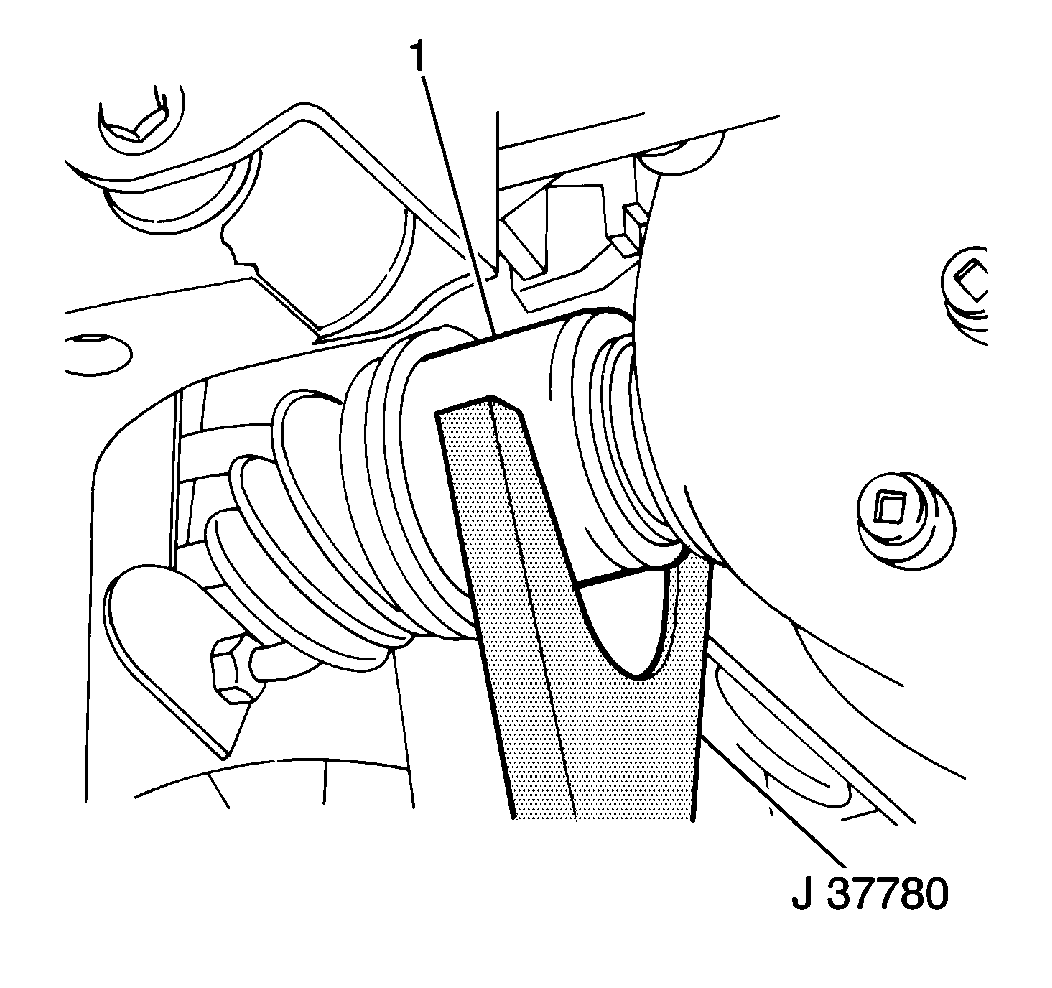
- Remove the right side drive axle from the front differential housing using the J 37780. If the right side drive axle does not separate from the differential housing using J 37780, extend the length of J 37780 using a pipe to provide more leverage to get the axle shaft retaining ring past the differential gear. The retaining ring may break during the axle shaft removal.
- On the left drive axle, make a reference mark (2) on the following components in order to ensure correct installation.
- Remove the left side drive axle flange bolts and position drive axle aside.
- Disconnect the vent hoses from the front axle housing.
- Remove the front propeller shaft to front axle bolts.
- Remove the front propeller shaft.
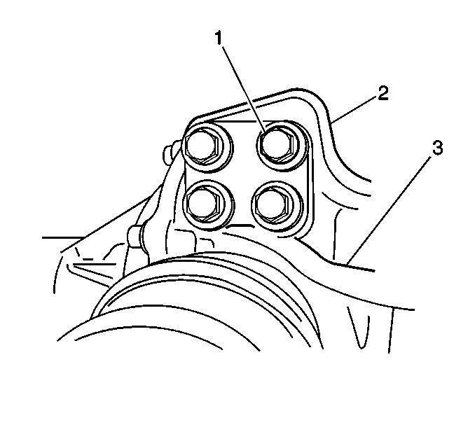
- Remove the front differential rear mount nuts and bolts (1).
- Remove the mount (2).
- Support the front differential for removal.
- Remove the front differential to the right side mount bolts.
- Remove the front differential to the left side mount bolts.
- Lower the front differential with assistants.
- Remove the left side output shaft axle from the differential housing.
- Remove the 6 differential carrier bolts and the two reamer bolts from the front axle housing.
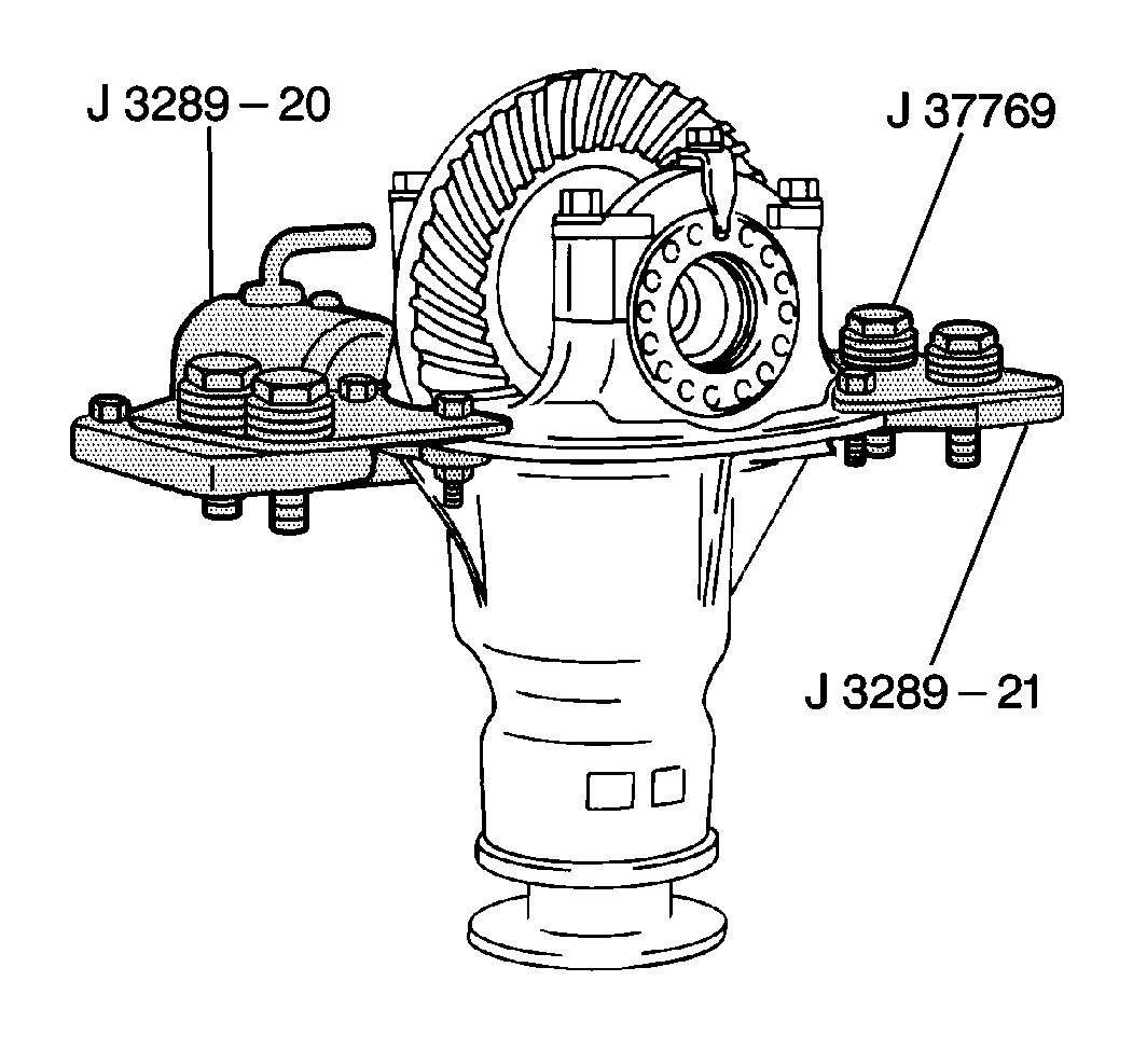
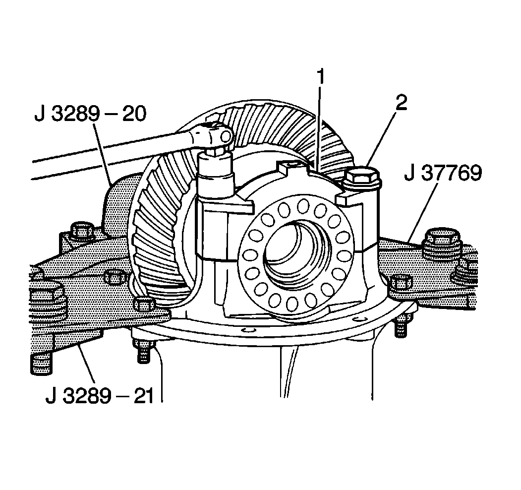
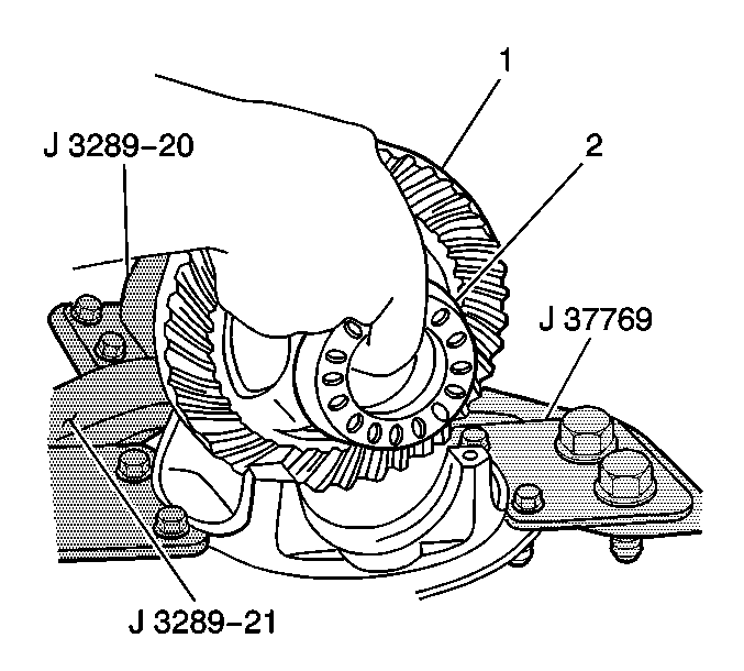
- Install the J 3289-21 to the differential carrier with the J 37769.
- Place the differential carrier and the holding fixture into the J 3289-20.
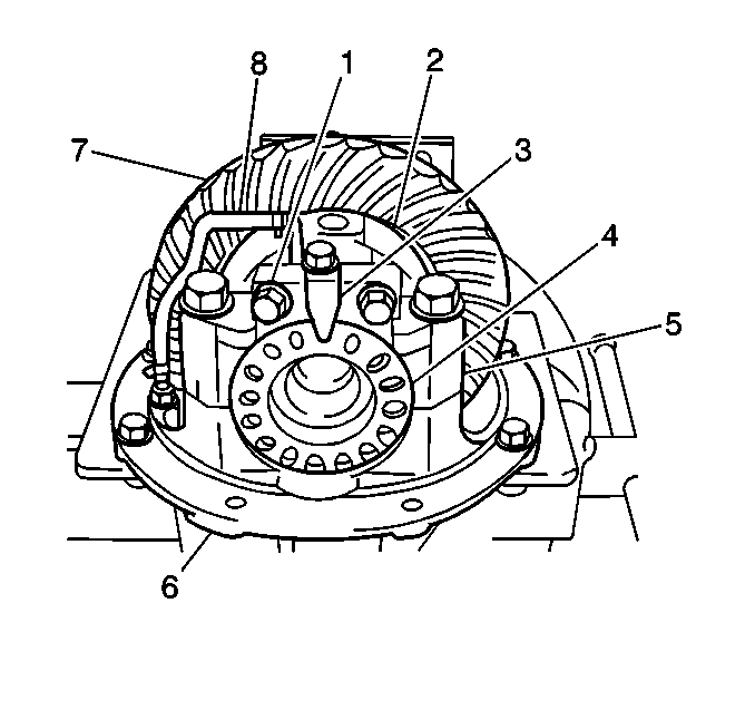
- Inscribe alignment marks on the differential side bearing caps to ensure proper assembly.
- Remove the 2 bolts (1) and the side bearing lock plates (3) from the differential carrier.
- Remove the differential inner air hose (8).
- Remove the 4 bolts (2) and the side bearing caps (1) from the differential carrier.
- Remove the side bearing adjusters from the differential carrier.
- Remove the differential ring gear and the case from the differential carrier.
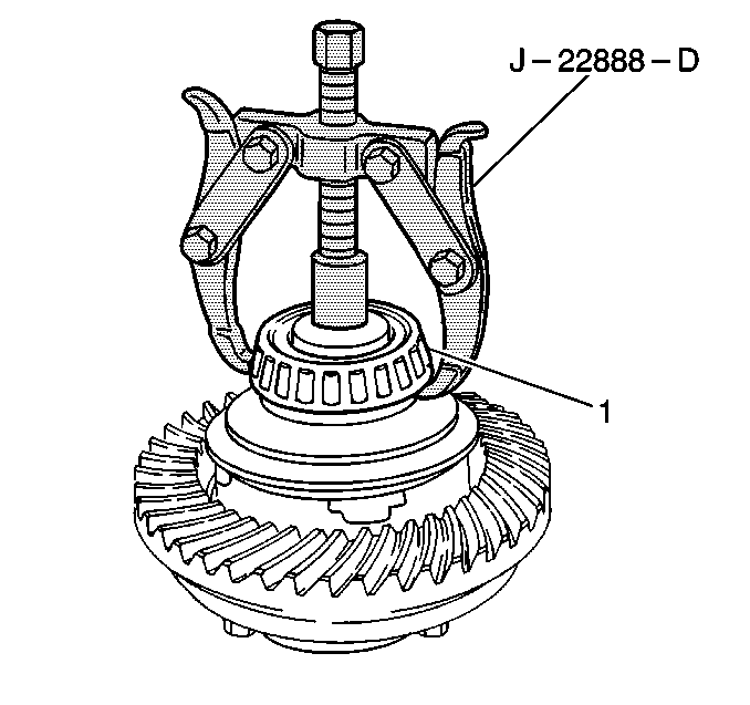
- Remove the side bearings (1) from the differential case using the J 22888-D with the J 8107-4.
- Remove the actuator.
- Remove the 10 bolts and the ring gear from the differential case.
- Install the ring gear (2) to the differential case. Secure with 10 bolts (1).
- Install the actuator to the differential case assembly.
- Install the side bearing (1) on the left side of the differential case assembly (2) using the J 37758 with the J 8092. Place the differential case assembly on the hydraulic press.
- Install the side bearing (1) on the right side of the differential case assembly (2) using the J 24433 with the J 8092 and J 8107-4. Place the differential case assembly on the hydraulic press using the J 8107-4 for support and to protect the left differential side bearing.
- Install the differential case assembly into the differential carrier.
- Install both side bearing adjusters (2) on the side bearing races.
- Install both side bearing caps onto the differential carrier and secure with the four side bearing cap bolts.
- Perform the differential side bearing preload adjustment using the procedure listed below.
- Perform the backlash inspection and adjustment using the procedure listed below.
- Install the differential inner air hose.
- Install the side bearing lock plates and the 2 bolts to the differential carrier.
- Remove the holding fixture and adapters from the differential carrier.
- Apply RTV silicone sealer, P/N 1052917, or equivalent, to the differential carrier mating surface on the front axle housing.
- Install the differential carrier (1) into the front axle housing (2).
- Install the 6 differential carrier bolts and the two reamer bolts.
- Install the left side output shaft axle to the differential housing.
- Raise the front differential housing with assistants and support with a suitable hydraulic jack.
- Install the front differential mount to left mounting bolts.
- Install the front differential mount to right mounting bolts.
- Remove the hydraulic jack from supporting the front differential housing.
- Install the front differential rear mount and the nuts and bolts.
- Install the front propeller shaft and bolts.
- Connect the vent hoses.
- Install the differential side joint flange of the drive axle shaft to the inner axle shaft flange.
- Secure the flange bolts and nuts.
- Install the new retaining ring and right drive axle shaft to the differential housing.
- Use a hydraulic jack in order to support the front control arm.
- Install the right steering knuckle/hub assembly.
- Install the lower control ball joint to the knuckle.
- Install the new right ball joint lock nut.
- Install the right strut bracket to steering knuckle bolts and nuts.
- Remove the hydraulic jack.
- Install the left and right stabilizer shaft and bushing to the control arm. Install the stabilizer shaft link nuts.
- Install the caliper and bolts to the mounting bracket.
- Install the drive axle shaft spindle washer onto the drive axle shaft.
- Install the drive axle shaft snap ring onto the end of the drive axle.
- Apply RTV silicone sealant, P/N 1052366, or equivalent, to the flange.
- Install the 6 flange bolts.
- Install the right outer tie rod end to the steering knuckle and the new lock nut.
- Install the front wheel speed sensor to the steering knuckle.
- Install the retaining bolt.
- Connect the front wheel speed sensor electrical connector.
- Install the right front wheel.
- Install the front axle housing drain plug into the front axle housing.
- Remove the front axle housing oil level/filler plug from the front axle housing.
- Refill the front axle housing with approximately 1 liter (1 qt) of 80W-90 GL5 lubricant, P/N 12345977 (in Canada, use P/N 10953482), or equivalent.
- Install the front axle housing oil level/filler plug into the front axle housing.
- If the vehicle is equipped with an engine skid plate, install the front skid plate to the vehicle. Secure the skid plate with 4 bolts.
- Lower the vehicle.


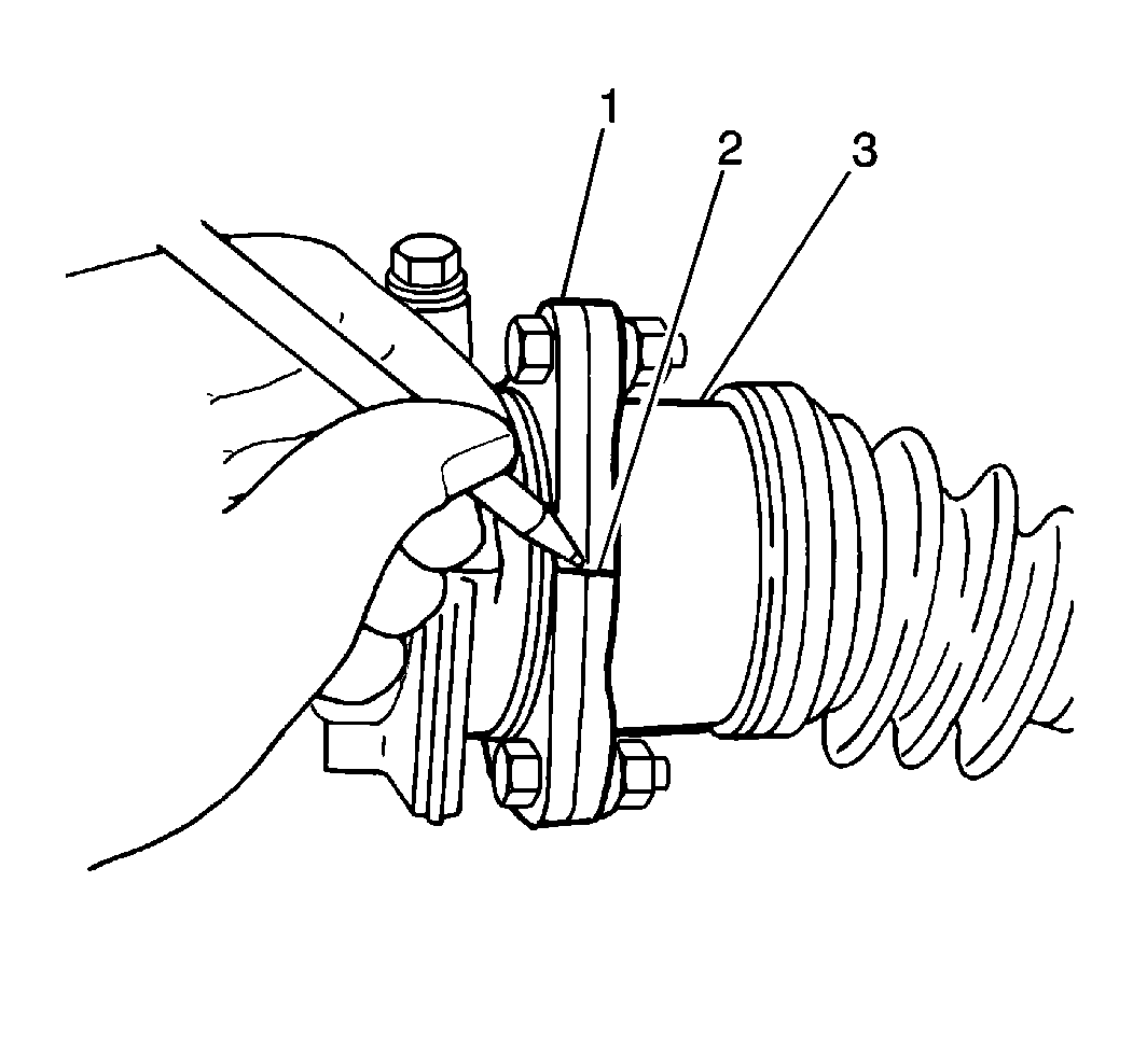
| • | The inner drive axle flange (1). |
| • | The differential side joint flange (3) of the drive axle shaft. |
Important: If during the right side drive axle removal, the retaining ring breaks, be sure to remove any material that may have fallen into the differential carrier.
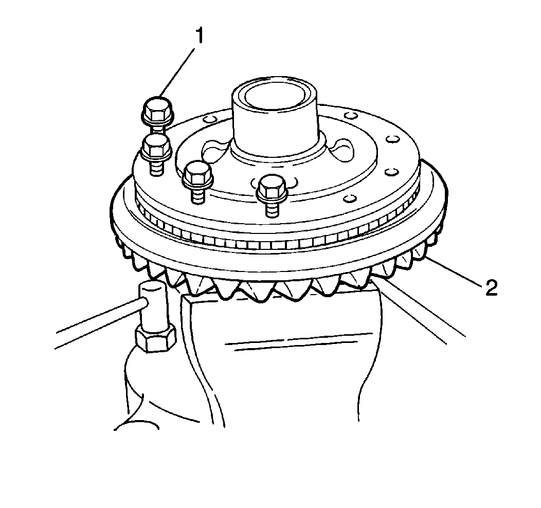
Important: Apply P/N 12345493 (in Canada, use P/N 10953488), or equivalent, to the threaded portion of each ring gear bolt being installed into the differential case.
Tighten
Tighten the ring gear bolts to 85 N·m (63 lb ft).
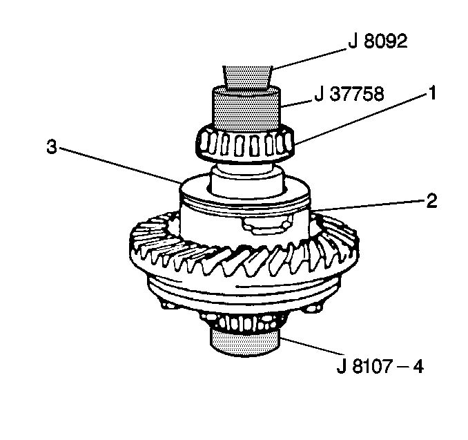
Use the J 37758 with the J 8092 in order to place the left differential side bearing on the left differential case with the tapered side up and slowly press the left differential side bearing onto the left differential case.
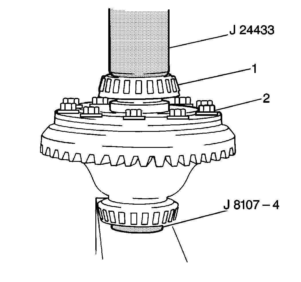
Use the J 24433 with the J 8092 in order to place the right differential side bearing on the right differential case with the tapered side up and slowly press the right differential side bearing onto the right differential case.
Tighten
Tighten the differential side bearing cap bolts to 15 N·m
(11 lb ft).
Tighten
Tighten the side bearing lock plate bolts to 13 N·m (10 lb ft).

Tighten
Tighten the differential carrier bolts to 23 N·m (17 lb ft).
Tighten
Tighten the bolts to 50 N·m (37 lb ft).
Tighten
Tighten the bolts to 50 N·m (37 lb ft).
Tighten
Tighten the front differential rear mount bolts and nuts to 50 N·m
(37 lb ft).
Tighten
Tighten the propeller shaft bolts to 50 N·m (37 lb ft).
Be sure to align the reference marks on the inner axle shaft flange and the differential side joint flange of the drive axle shaft.
Tighten
Tighten the differential side joint bolts and nuts to 55 N·m
(41 lb ft).
Tighten
Tighten the nut to 60 N·m (43 lb ft).
Tighten
Tighten the nuts and the bolts to 95 N·m (69 lb ft).
Tighten
Tighten the link nuts to 29 N·m (21 lb ft).
Tighten
Tighten the bolts to 27N·m (20 lb ft).
Tighten
Tighten the flange bolts to 48 N·m (35 lb ft).
Tighten
Tighten the nut to 43 N·m (31 lb ft).
Tighten
Tighten the bolt to 7.8 N·m (69 lb in).
Tighten
Tighten the drain plug to 23 N·m (17 lb ft).
Tighten
Tighten the oil level/filler plug to 40 N·m (30 lb ft).
Tighten
Tighten the skid plate bolts to 54 N·m (40 lb ft).
Differential Side Bearing Preload
Side bearing preload is necessary to maintain the correct bearing pressure on both sides of the differential case so that the differential case will turn evenly at all speeds. Side bearing preload is measured by the distance between the side bearing caps or case spread. Once the differential side bearing preload has been adjusted, it must be maintained throughout the differential backlash adjustment procedure. Setting differential backlash is very important to the service life of the ring and the pinion gears. Setting differential backlash determines the amount of depth at which the ring gear will contact the pinion gear. This determines the distance of the pinion gear teeth from the drive side and the coast side of the ring gear teeth. The deeper the gears mesh, the less amount of backlash. The more shallow the mesh, the more backlash is created. This adjustment is vital for correct differential operation.
Tools Required
| • | J 8001 Dial Indicator Set |
| • | J 37760 Spanner Wrench |
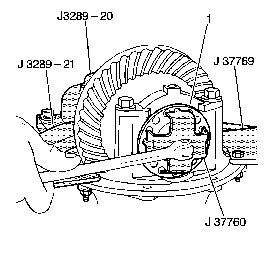
- Use the J 37760 until it no longer makes contact with the right differential side bearing race in order to loosen the right differential side bearing adjuster (1).
- Use the J 37760 until the ring gear is fully engaged with the pinion gear (0.000 backlash) in order to tighten the left differential side bearing adjuster.
- Inspect the right adjuster. Ensure the right adjuster is not making contact with the right side bearing race.
- Grasp the pinion flange and rotate the pinion gear several times in order to inspect the pinion gear for binding.
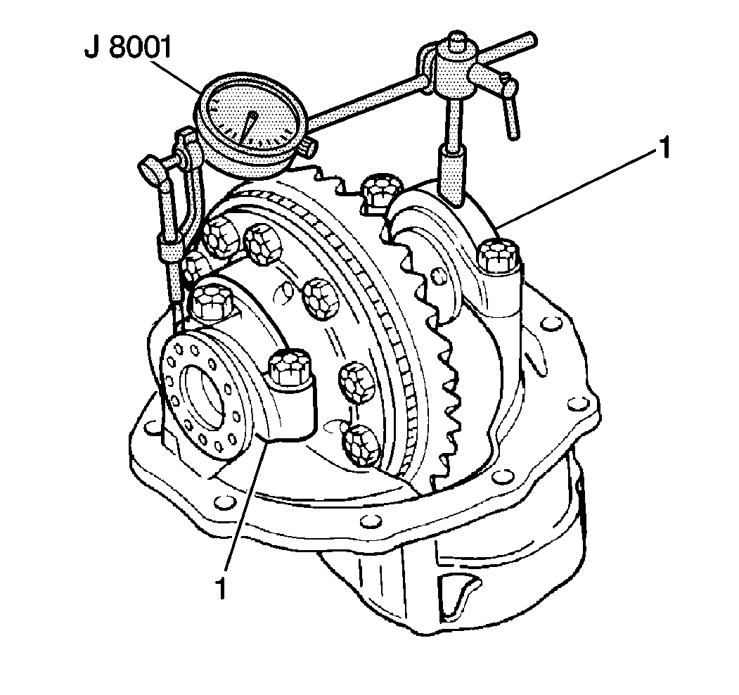
- Install J 8001 on the differential carrier between the center of each side bearing cap (1) to measure case spread.
- Use J 37760 until the adjuster makes contact with the right side bearing race in order to tighten the right adjuster.
- Rotate the J 8001 adjustable face until the indicator needle reads 0.
- Adjust the differential side bearing preload by tightening the right adjuster using J 37760 until the J 8001 reads 0.0508-0.1524 mm (0.002-0.006 in). This specification indicates the amount of case spread between the centers of both side bearing caps.
Backlash Inspection and Adjustment
Tools Required
| • | J 3289-20 Holding Fixture |
| • | J 3289-21 Differential Holding Fixture |
| • | J 37769 Differential Holding Fixture Adapters |
| • | J 37760 Spanner Wrench |
| • | J 8001 Dial Indicator Set |
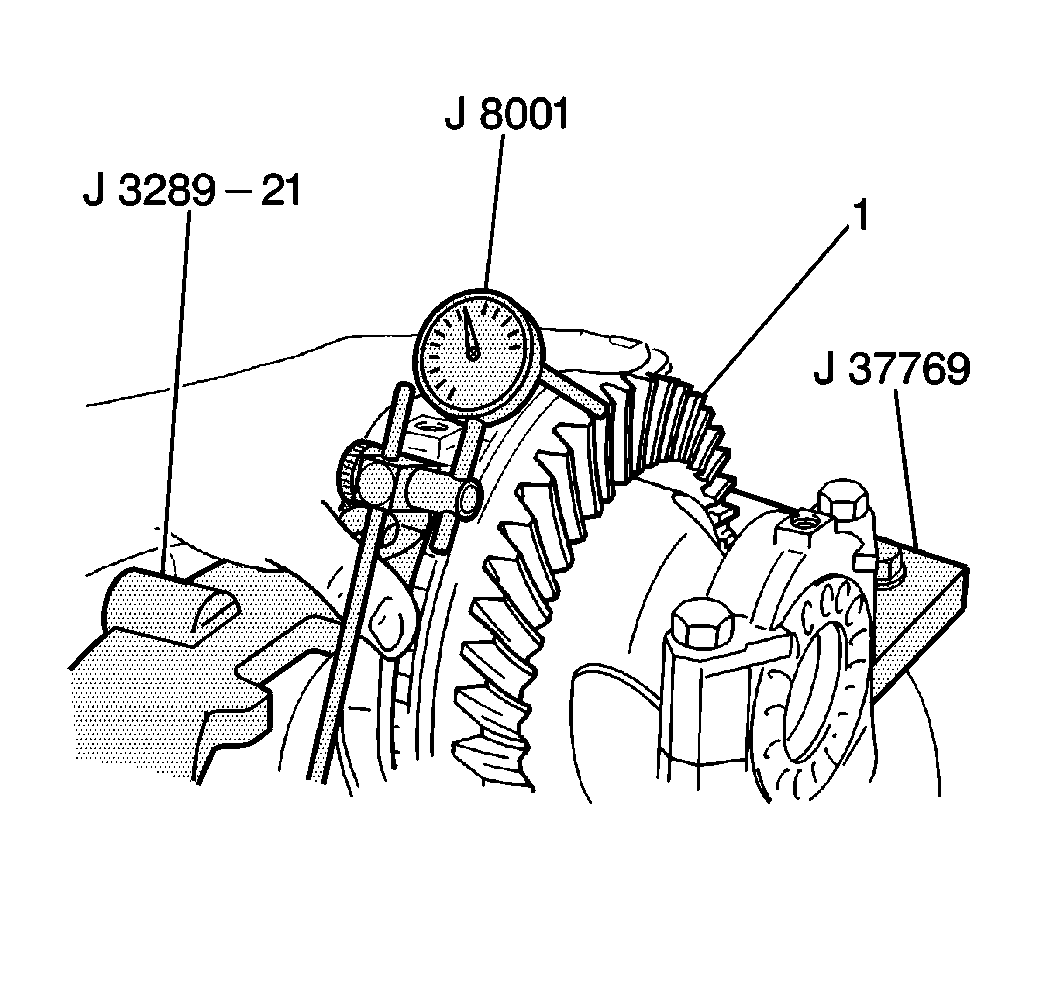
- Install the J 8001 to the differential carrier with the dial indicator plunger against a ring gear tooth.
- Hold the pinion gear stationery.
- Move the ring gear (1) back and forth as far as it will travel without turning the pinion gear.
- Observe the J 8001 while moving the ring gear back and forth as previously described. Differential backlash should be within 0.013 to 0.018 mm (0.005 to 0.007 in).
- Correct the specifications by following the directions below:
- Continue with the adjustment of specifications until the most accurate differential backlash is obtained.
- Install both side bearing lock plates and secure with two bolts.
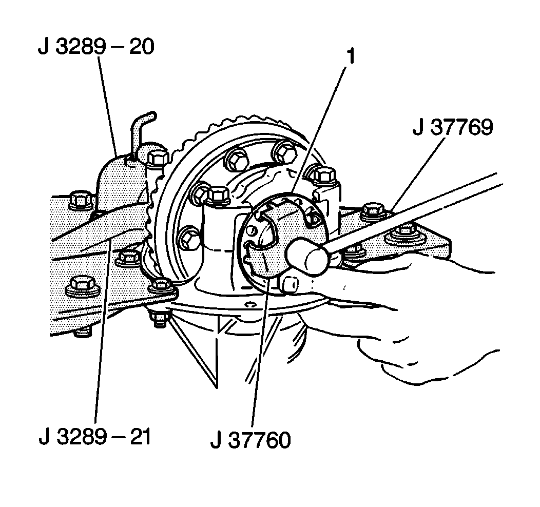
Important: In order to preserve the differential side bearing preload, any time a side bearing adjuster is loosened, the other adjuster MUST be tightened the same amount. The last motion of this adjustment must be in a tightening direction.
Above Specification
| • | Loosen the left side bearing adjuster approximately ¼ turn. |
| • | Tighten the right side bearing (1) adjuster approximately ¼ turn using the J 37760. |
| • | This procedure moves the ring gear close to the pinion gear in order to cause a tighter mesh and less backlash. |
Below Specification
| • | Loosen the right side bearing adjuster approximately ¼ turn. |
| • | Tighten the left side bearing adjuster approximately ¼ turn using the J 37760. |
| • | This procedure moves the ring gear away from the pinion gear in order to cause a looser mesh and more backlash. |
Tighten
Tighten the differential side bearing cap bolts to 60 N·m
(44 lb ft).
Tighten
Tighten both of the side bearing lock plate bolts to 13 N·m
(10 lb ft).
Parts Information
Part Number | Description |
|---|---|
91176222 | Front Differential Case |
91175518 | Actuator, Front Differential |
96057727 | Bearings, Side Differential |
91174735 | Ring, Front Wheel Drive Shaft Retaining |
12345977 (U.S.) 10953482 (Canada) | 80W-90 GL5 Lubricant (2 Per Vehicle) |
Parts are currently available from GMSPO.
Warranty Information
For vehicles repaired under warranty, use:
Labor Operation | Description | Labor Time |
|---|---|---|
F2222 | Case, Front Differential - Replace | Use Published Labor Operation Time |
