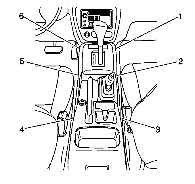
Removal Procedure
Caution: This vehicle is equipped with a Supplemental Inflatable Restraint (SIR) System. Failure to follow the correct procedure could cause the following conditions:
| • | Unnecessary SIR system repairs |
| • | Refer to SIR Component Views in order to determine if you are performing service on or near the SIR components or the SIR wiring. |
| • | If you are performing service on or near the SIR components or the SIR wiring, disable the SIR system. Refer to Disabling the SIR System. |
- Disable the SIR system. Refer to
Disabling the SIR System
in SIR.

- Remove the following from
the floor:
| • | The 2 plastic retaining clips (2,5) |

- Remove the following components
from the steering column:
| 3.2. | The steering column upper cover |
| 3.3. | The steering column lower cover |
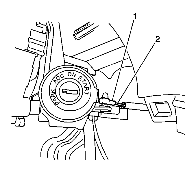
- Remove the bracket retaining screw (2) from the ignition
switch.
- Remove the interlock cable (1) from the ignition switch.
- Remove the interlock cable nut.
- Remove the interlock cable at the manual selector.
- Remove the interlock cable (1) out from under the instrument
panel.
- Remove the interlock cable from under the carpet.
- Remove the interlock cable from the interlock cable bracket at
the manual selector.
- Inspect the interlock cable for fraying or kinks.
- Replace the cable as necessary.
Installation Procedure

- Route the interlock cable
under the carpet to the manual selector and under the instrument panel
to the ignition switch.
- Place the manual selector lever in the NEUTRAL position.
- Turn the ignition switch to ACC.
- Install the interlock cable end to the ignition switch (1).
- Secure the interlock cable end with the bracket retaining screw.
- Adjust and tighten the screw in order to get the correct tension.
- Install the steering column upper cover and the steering column
lower cover to the steering column.
- Secure the covers to the steering column with the screws.
- Install the interlock cable end.
Notice: Use the correct fastener in the correct location. Replacement fasteners
must be the correct part number for that application. Fasteners requiring
replacement or fasteners requiring the use of thread locking compound or sealant
are identified in the service procedure. Do not use paints, lubricants, or
corrosion inhibitors on fasteners or fastener joint surfaces unless specified.
These coatings affect fastener torque and joint clamping force and may damage
the fastener. Use the correct tightening sequence and specifications when
installing fasteners in order to avoid damage to parts and systems.
Important: After tightening the interlock cable nut, make sure that the ignition
switch can be turned from ACC to LOCK and the key can be removed from the
ignition with the manual selector lever shifted to the PARK
position. Also verify that with the manual selector lever
in any position other than PARK, the ignition switch CANNOT
be turned from ACC to LOCK.
- Tighten the interlock cable nut.
Tighten
Tighten the nut to 13 N·m (115 lb ft).

- Install the console box
to the floor.
- Secure the console box with 2 plastic retaining clips (2,5)
and 4 screws (1,6,3,4).
- Enable the SIR. Refer to
Enabling the SIR System
in SIR.


