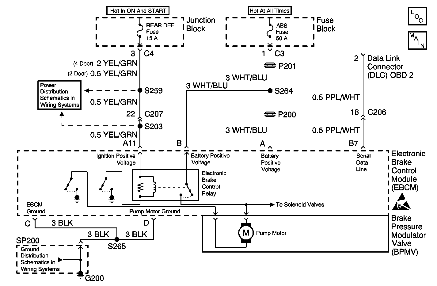
Circuit Description
The service technician must begin diagnosis of any ABS complaint with the ABS Diagnostic System Check.
The diagnostic system check directs the service technician to the next logical step in diagnosing the complaint.
Diagnostic Aids
Communication with the EBCM is not possible when excessive resistance exists in the following components:
| • | Grounds |
| • | The power supply circuits |
If communication with the EBCM is not possible, perform the following actions:
| • | Verify that the EBCM ground connection is good. |
| • | Verify that no excessive resistance exists in any of the power supply circuits. |
The following list contains items that need to be inspected when diagnosing this system:
| • | Open DEF Fuse |
| • | Open ABS Fuse |
| • | Clean, tight G200 |
Excessive resistance in the following circuits will not allow communication with the EBCM:
| • | Battery feed |
| • | Switched ignition |
| • | Ground |
| • | Serial data line |
If communication with the EBCM is not possible with a scan tool, ensure these circuits are in good condition and that there is no excessive resistance. Also check the EBCM connectors for poor connector terminal contact. Refer to Data Link Communications System Check in Data Link Communications.
If an intermittent malfunction exists, refer to Testing for Intermittent Conditions and Poor Connections in Wiring Systems.
Test Description
The numbers below refer to the step numbers on the diagnostic table.
-
This test determines if the scan tool can communicate with any other modules on the serial data line.
-
Tests for a short to ground in the ignition positive voltage circuit.
-
Tests the EBCM ground circuit for an open or high resistance.
-
Tests the ignition positive voltage circuit for an open or high resistance.
Step | Action | Value(s) | Yes | No |
|---|---|---|---|---|
1 | Did you perform the ABS Diagnostic System Check? | -- | Go to Step 2 | |
Does the scan tool communicate with any other modules? | -- | Go to Step 3 | ||
3 |
Is the fuse open? | -- | Go to Step 4 | Go to Step 5 |
Did you find and correct the condition? | -- | Go to Testing for Intermittent Conditions and Poor Connections in Wiring Systems | ||
5 | Inspect the EBCM ground G200, making sure that the ground is clean and torqued to the proper specification. Refer to Wiring Repairs in Wiring Systems. Did you find and correct the condition? | -- | Go to Step 6 | |
Did you find and correct the condition? | -- | Go to Step 7 | ||
Test the ignition positive voltage circuit for an open or high resistance. Refer to Circuit Testing and Wiring Repairs in Wiring Systems. Did you find and correct the condition? | -- | Go to Step 8 | ||
8 | Inspect for poor connections at the harness connector of the EBCM. Refer to Testing for Intermittent Conditions and Poor Connections and Connector Repairs in Wiring Systems. Did you find and correct the condition? | -- | Go to Step 9 | |
9 | Replace the EBCM. Refer to Electronic Brake Control Module Replacement . Did you complete the replacement? | -- | -- |
