Removal Procedure
- Discharge and recover the refrigerant. Refer to Refrigerant Recovery and Recharging .
- Disable the SIR. Refer to Disabling the SIR System in SIR.
- Disconnect the negative battery cable.
- Remove the instrument panel carrier. Refer to Instrument Panel Carrier Replacement in Instrument Panel, Gauges and Console.
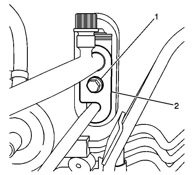
- Remove the bolt (1) and slide the plate (2) counterclockwise in order to remove the evaporator inlet and outlet tubes at the bulkhead.
- Cap the open refrigerant lines in order to prevent dirt and moisture from entering the refrigeration system.
- Disconnect the evaporator temperature sensor electrical connector from the compressor control module.
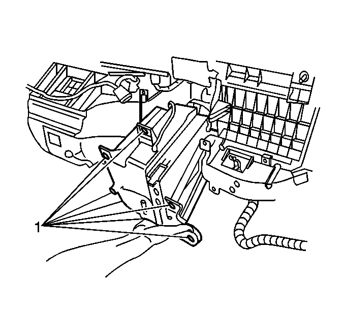
- Remove the 6 screws and 2 nuts (1).
- Remove the evaporator case from the vehicle.
- Remove the 5 screws and the insulation from the evaporator case.
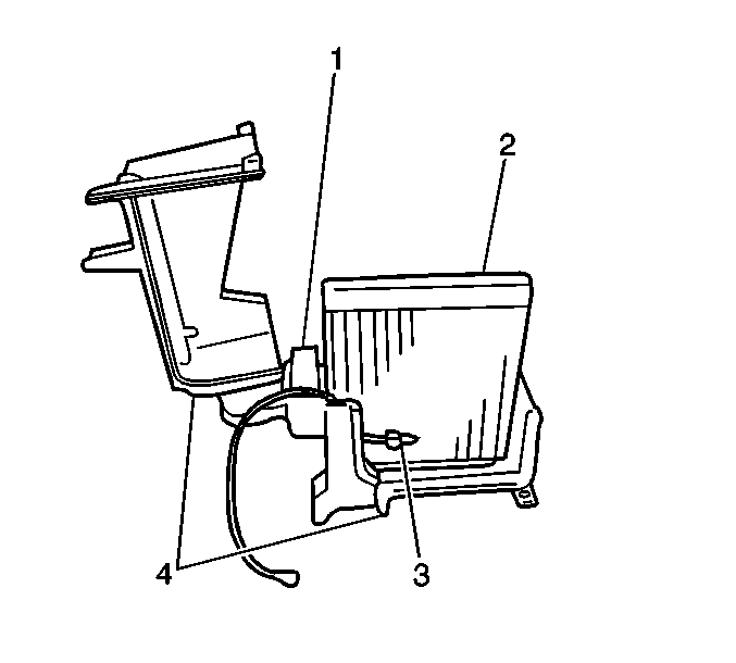
- Separate the evaporator case halves (4).
- Remove the evaporator from the lower case.
- Remove the expansion valve (1) from the evaporator by removing the 2 bolts.
- Remove the evaporator temperature sensor (3) from the evaporator.
Caution: This vehicle is equipped with a Supplemental Inflatable Restraint (SIR) System. Failure to follow the correct procedure could cause the following conditions:
• Air bag deployment • Personal injury • Unnecessary SIR system repairs • Refer to SIR Component Views in order to determine if you are performing service on or near the SIR components or the SIR wiring. • If you are performing service on or near the SIR components or the SIR wiring, disable the SIR system. Refer to Disabling the SIR System.
Caution: Unless directed otherwise, the ignition and start switch must be in the OFF or LOCK position, and all electrical loads must be OFF before servicing any electrical component. Disconnect the negative battery cable to prevent an electrical spark should a tool or equipment come in contact with an exposed electrical terminal. Failure to follow these precautions may result in personal injury and/or damage to the vehicle or its components.


Installation Procedure
- Install the evaporator to the lower case.
- Install the evaporator temperature sensor (3) to the evaporator.
- Install the expansion valve (1) to the evaporator. Secure with the 2 bolts.
- Connect the evaporator case halves (4). Secure the case halves with the 5 screws.
- Install the evaporator case to the vehicle.
- Install the 5 screws and 2 nuts (1).
- Connect the evaporator temperature sensor electrical connector to the compressor control module.
- Install new O-rings to the evaporator pipe fittings. Coat the new O-rings with mineral base 525 viscosity refrigerant oil.
- Connect the evaporator inlet and outlet pipes at the bulkhead. Slide the plate (2) clockwise and secure with the bolt (1).
- Install the instrument panel carrier. Refer to Instrument Panel Carrier Replacement in Instrument Panel, Gauges and Console.
- Enable the SIR. Refer to Enabling the SIR System in SIR.
- Connect the negative (-) battery cable.
- Evacuate and recharge the air conditioning system. Refer to Refrigerant Recovery and Recharging .
- Operate the A/C system and inspect for refrigerant leaks. Refer to Leak Testing .


Notice: Use the correct fastener in the correct location. Replacement fasteners must be the correct part number for that application. Fasteners requiring replacement or fasteners requiring the use of thread locking compound or sealant are identified in the service procedure. Do not use paints, lubricants, or corrosion inhibitors on fasteners or fastener joint surfaces unless specified. These coatings affect fastener torque and joint clamping force and may damage the fastener. Use the correct tightening sequence and specifications when installing fasteners in order to avoid damage to parts and systems.
Tighten
Tighten the evaporator case mounting bolts and nuts to 10 N·m
(89 lb in).

