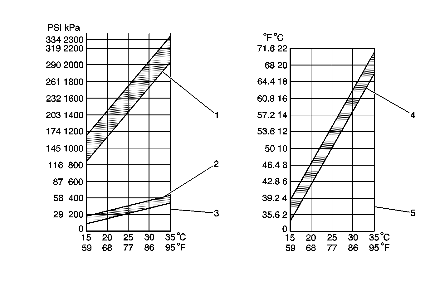
For 1990-2009 cars only
Tools Required
| • | J 39183-C R-134a Manifold Gauge Set |
| • | J 6742-03 Thermometer Dial |
- Turn the ignition switch to LOCK.
- Apply the parking brake.
- Connect the J 39183-C manifold gauge set High side (RED) and Low side (BLU) hoses to their respective service ports on the vehicle.
- Start the engine and let it warm up to normal operating temperature. Let the engine run at normal idle speed.
- Keep all of the doors and windows and the hood open.
- Set the temperature control to the coldest position.
- Set the mode control to the IP outlet position.
- Set the blower intake to the recirculate position
- Set the blower speed to the highest position.
- Press the A/C switch to the ON position.
- Place the J 6742-03 thermometer dial probe through the IP center outlet.
- Run the A/C system until the outlet air temperature reaches the lowest temperature. This should take approximately 3 minutes.
- Monitor the thermometer and record the center outlet air temperature when it stabilizes.
- Monitor the gauge set and record the refrigerant pressures when they stabilize. Normal operating pressures should be within the range below. However, on-vehicle operating pressures are affected by ambient temperature and humidity variables.
- Turn the blower speed selector to OFF.
- Turn the ignition switch to LOCK.
- Remove the thermometer.
- Disconnect the manifold gauge set.
Important: Perform the A/C system performance test only under the following conditions:
• The vehicle is not exposed to direct sunlight. • The ambient temperature is within 30-35°C (86-95°F).
High Side Pressure Range
1275-1670 kPa (185-244 psi)
Low Side Pressure Range
150-300 kPa (21-43 psi)
A/C Inlet Temperature
30-35°C (86-95°F)
Compare the recorded High and Low side refrigerant system pressures and the outlet air temperature with the table below. If the recorded values are not within the specifications, refer to TXV A/C System Diagnosis (Insufficient Cooling) .

