Tools Required
J 43846 Actuator
Pressure Gauge
- Raise the vehicle. Support the vehicle. Refer to
Lifting and Jacking the Vehicle
in General Information.
- If the vehicle is equipped with an engine skid plate, remove the
four bolts that hold the skid plate in place. Remove the front skid plate
from the vehicle.

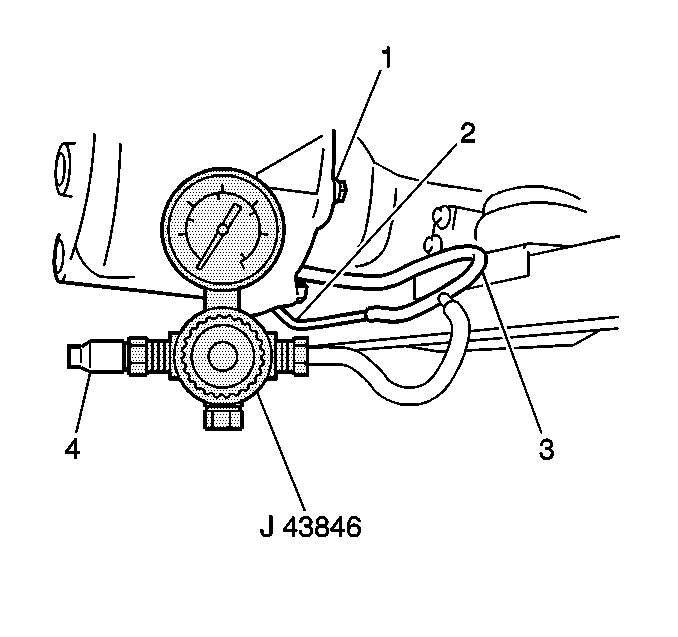
- Install theJ 43846
with the air hose connecting between
the air pump assembly and the front differential actuator.
- Tighten the adjusting knob as far as it stops.
Important: Be careful not to bend any part of the hose.
- Turn on the ignition switch and shift transfer lever from 2H to 4H range.
- Make sure to check that the motor of the actuator starts running
(a running sound can be heard) within 1 second and it stops when the
actuator pressure gauge indicates specified pressure. Check for
air leakage during the procedure. Pressure specification is: 38.0 kPa
(5.40 -- 8.25 psi).
- Check that the pressure indicated on the gauge drops as soon as
the transfer lever is shifted to the 2H position.
- Start the motor of the actuator pump by shifting the transfer
lever to the 4H position again. Loosen the adjusting knob to lower the pressure
on the gauge. The actuator motor should start to run again and stop
in about 4 seconds.
- With the adjusting knob of the actuator pressure gauge loosened,
shift the transfer shift lever to neutral or the 2H position and then 4L or
4H position. Pump motor should stop in about 10 seconds after
the motor starts to run.

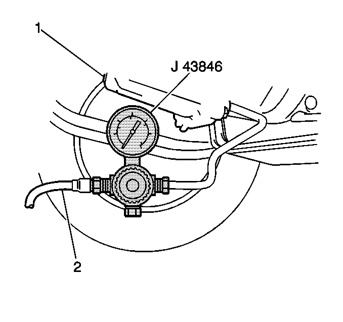
- Disconnect the air hose (2)
from the actuator pump assembly and connect it the front differential air
hose inlet. Loosen the adjusting knob.
- Connect the air compressor air hose to the actuator pressure gauge.
- Compress air into the actuator pressure gauge and turn knob to
obtain specified pressure. Specified pressure : 38.0 kPa (5.40 psi)
- While both wheels are lifted off the ground, turn one of the front
wheels by hand and check the other wheel for the following:
| • | When applying pressure to the actuator pump the other front wheel
should turn in the direction opposite to the wheel being turned by hand. |
| • | When the actuator pump is not working (by not applying pressure)
the other front wheel should remain stationary while the wheel turned by hand
is turning. |

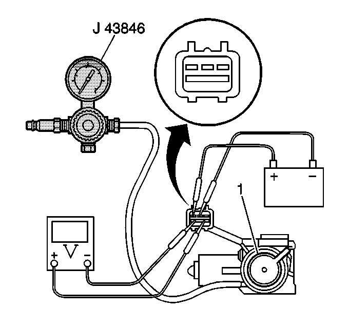
| • | Install the actuator pressure
gauge to the actuator pump assembly (1) . |
| • | Install a voltmeter and the battery to the pump assembly (1) . |
| • | Tighten the adjusting knob as far as it will stop and the air
check side opening by a hose as a blind plug. |
| • | Check that the actuator assembly motor starts to run (a running
sound can be heard) when the battery is connected and when it stops when specified
pressure is obtained. Specified pressure is: 38.0- 58.0 kPa
(5.40 -- 8.25 psi). |
| • | Ensure that the voltmeter is within specifications
when the motor is running should be about 0v and when the motor has stopped
it should be about 10 -- 14v. |


