GM Service Manual Online
For 1990-2009 cars only

All models utilize an internal regulator charging system. The integrated circuit (IC) regulator is a solid state unit that is mounted inside the generator to the rear end frame. All regulator components are enclosed in a solid mold to protect them from heat and corrosive elements.

The generator rotor bearings contain enough grease to eliminate the need for periodic lubrication. Two brushes carry current through two slip rings to the field coil mounted on the rotor. Stator windings are assembled inside a laminated core that form part of the generator drive end frame. A rectifier bridge that contains 6 diodes is connected to the stator windings. These diodes electrically change stator AC voltage into DC voltage. This DC voltage is then transmitted to the generator output terminal. Two neutral diodes are utilized to smooth out voltage fluctuations caused by varying generator speeds. A capacitor (condenser), mounted in the regulator, protects the rectifier bridge and neutral diodes. This capacitor also suppresses radio interference noise.

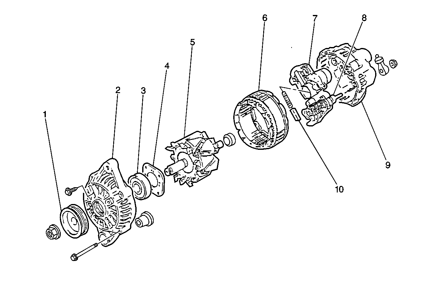
Figure 1:

Generator Disassembly


Object Number: 465464  Size: MF
(1)Pulley
(2)Front Housing
(3)Bearing
(4)Retainer
(5)Rotor
(6)Stator
(7)IC Regulator
(8)Rectifier
(9)Rear Housing
(10)Brush
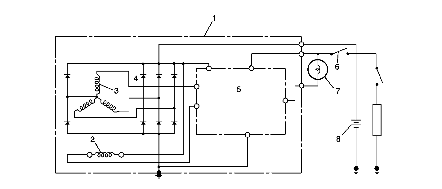
Figure 2:

70 Amp Generator Schematic


Object Number: 465468  Size: SF
(1)Generator with Regulator Assembly
(2)Field Coil (Rotor Coil)
(3)Stator Coil
(4)Diode
(5)IC Regulator
(6)Ignition Switch
(7)Charge Indicator Light
(8)Battery
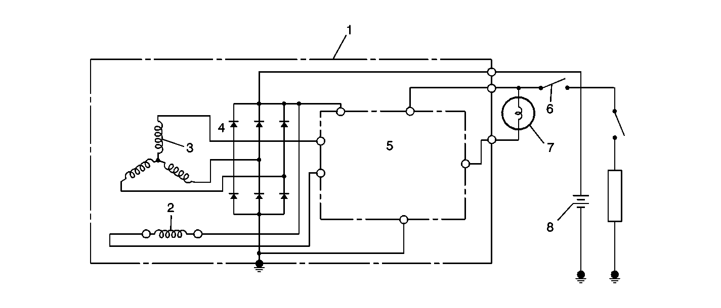
Figure 3:

60 Amp Generator Schematic


Object Number: 465477  Size: SF
(1)Generator with Regulator Assembly
(2)Field Coil (Rotor Coil)
(3)Stator Coil
(4)Diode
(5)IC Regulator
(6)Ignition Switch
(7)Charge Indicator Light
(8)Battery
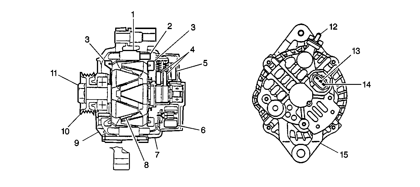
Figure 4:

Generator


Object Number: 465472  Size: SF
(1)Stator Core
(2)Stator Coil
(3)Rotor Fan
(4)Brushes
(5)Regulator
(6)Rectifier
(7)Rear Housing
(8)Field Coil
(9)Front Housing
(10)Pulley
(11)Pulley Nut
(12)Generator Output Terminal
(13)Ignition terminal
(14)Lamp Terminal
(15)Ground