For 1990-2009 cars only
Underhood Fuse Block Replacement Fuse Block
Removal Procedure
- Disconnect the negative battery cable.
- Remove the fuse block cover.
- Remove the bolt from the fuse block bracket.
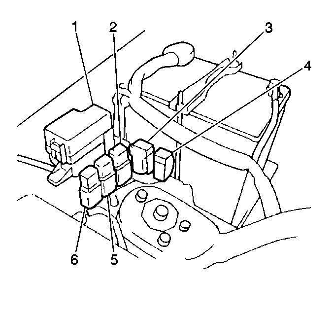
- Release the clip and slide the fuse block (1) from the bracket.
- Remove the 2 bolts and the battery positive wires from the fuse block. Note the correct terminal routing for installation.
- Disconnect the electrical connectors from the bottom of the fuse block.
Caution: Unless directed otherwise, the ignition and start switch must be in the OFF or LOCK position, and all electrical loads must be OFF before servicing any electrical component. Disconnect the negative battery cable to prevent an electrical spark should a tool or equipment come in contact with an exposed electrical terminal. Failure to follow these precautions may result in personal injury and/or damage to the vehicle or its components.
Installation Procedure
- Connect the electrical connectors to the bottom of the fuse block.
- Connect the battery positive wires to the fuse block. Secure with the 2 bolts.
- Install the fuse block (1) to the bracket. Secure with the bolt.
- Install the fuse block cover.
- Connect the negative battery cable.

Underhood Fuse Block Replacement A/CHarness
Removal Procedure
- Remove the relays from the fuse block bracket.
- Refer to
Main Harness
- Remove the harness from the retainers.
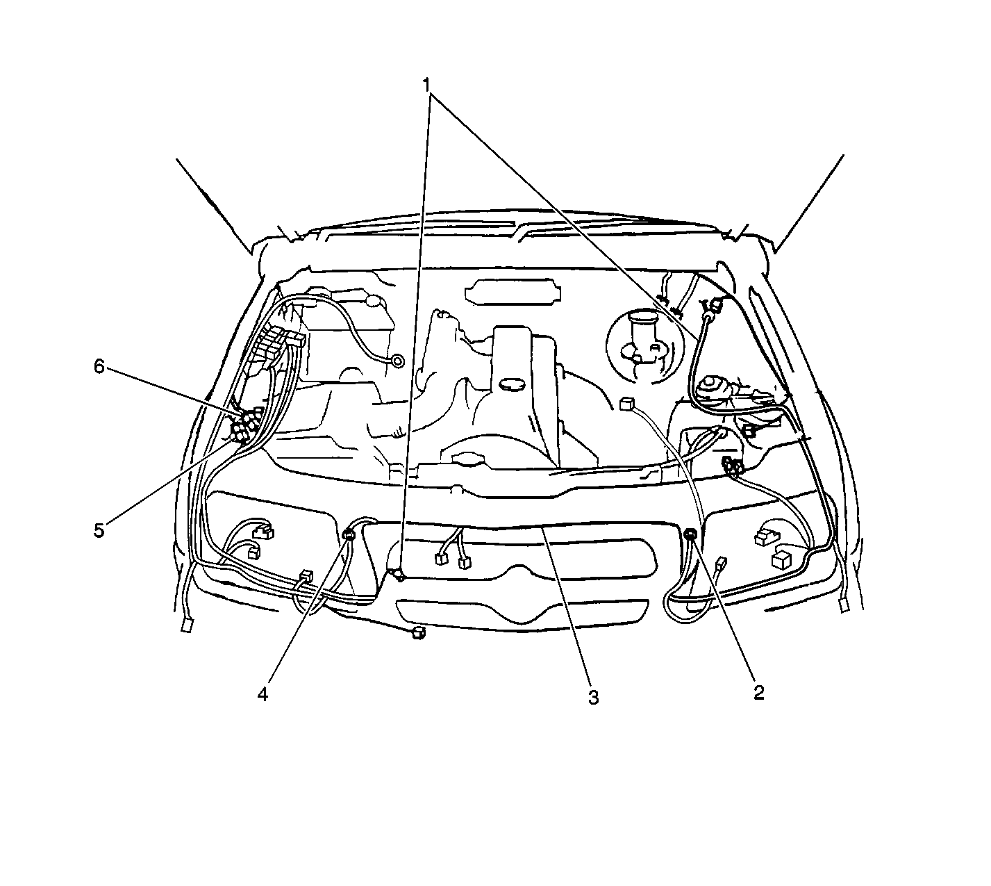
- Remove the harness (1) from the vehicle.

Disconnect the following:
| • | The air conditioning A/C relay |
| • | The A/C fuse |
| • | The A/C condenser fan relay |
| • | C101 |
| • | C103 |
| • | G105 next to the radiator |
| • | The refrigerant pressure switch |
| • | The A/C condenser fan motor |
| • | The A/C compressor clutch connector |
Installation Procedure
- Install the harness (1) to the vehicle.
- Install the harness to the retainers.
- Refer to
Main Harness

- Install the relays to the fuse block bracket.

Connect the following:
| • | The air conditioning A/C relay |
| • | The A/C fuse |
| • | The A/C condenser fan relay |
| • | C101 |
| • | C103 |
| • | G105 next to the radiator |
| • | The refrigerant pressure switch |
| • | The A/C condenser fan motor |
| • | The A/C compressor clutch connector |
Underhood Fuse Block Replacement Engine Harness
Removal Procedure
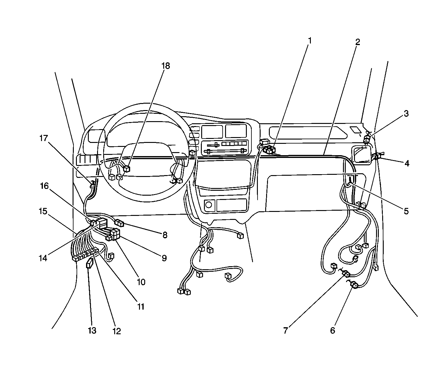
- Refer to Harness Routing Views in Wiring Systems.
- Disconnect C210. Refer to
Main Harness
- Disconnect C212. Refer to
Main Harness

- Disconnect C2, C3 and C4 from the powertrain control module (PCM).
- Remove the harness from the interior of the vehicle. Push the harness through the bulkhead grommet P100 into the engine compartment.
- Remove the harness from the retainers.
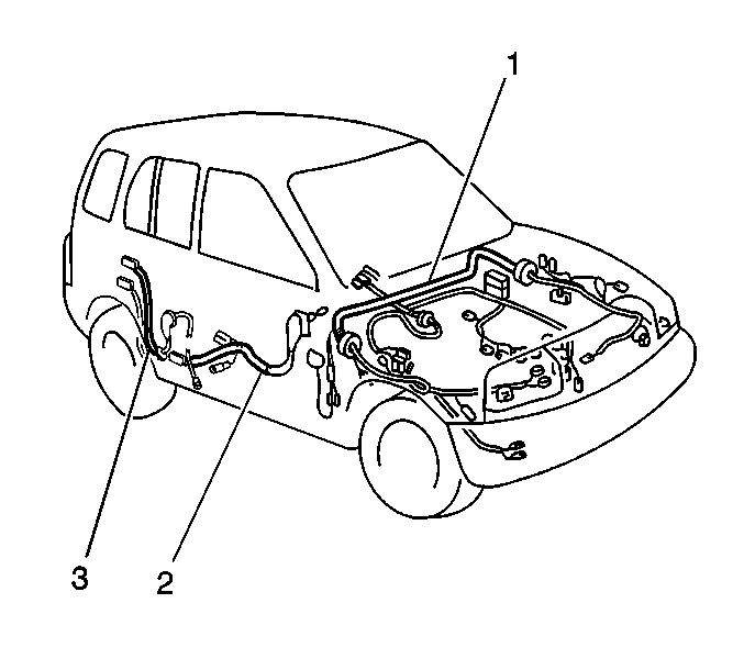
- Remove the harness (2) from the vehicle.
Disconnect the following electrical connectors:
| • | The intake air temperature (IAT) sensor |
| • | The mass air flow (MAF) sensor |
| • | The EVAP tank pressure control solenoid valve |
| • | The EVAP canister vent solenoid |
| • | The EVAP canister purge valve |
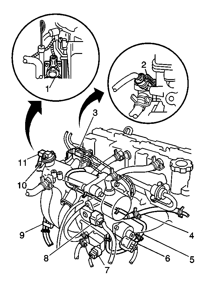
| • | The throttle position sensor (TPS) (8) |
| • | The idle air control (IAC) valve (6) |
| • | The power steering pressure switch |
| • | The generator |
| • | The starter motor |
| • | The crankshaft position (CKP) sensor |
| • | The exhaust gas recirculation (EGR) valve (1) |
| • | The manifold absolute pressure (MAP) sensor (11) |
| • | G102 |
| • | G103 (10) |
| • | The noise suppressor filter |
| • | The engine coolant temperature (ECT) sensor (2) |
| • | The heated oxygen (HO2S1) sensor |
| • | The heated oxygen (HO2S2) sensor (California emissions only) |
| • | The oil pressure switch |
| • | The camshaft position (CMP) sensor |
| • | The ignition coils |
| • | The fuel injector harness, C102 (3) |
| • | The back up lamp switch |
| • | The transmission range switch |
| • | The input shaft speed sensor |
| • | The 4 wheel drive low switch |
| • | The 4 wheel drive switch |
| • | The vehicle speed sensor (VSS) |
| • | The output shaft speed sensor |
| • | The torque converter clutch (TCC) solenoid/shift solenoid |
Installation Procedure
- Refer to Harness Routing Views in Wiring Systems.
- Install the harness to the retainers.
- Push the harness through the bulkhead grommet P100 into the interior of the vehicle.
- Connect C210. Refer to
Main Harness

- Connect C212. Refer to
Main Harness

- Connect C2, C3 and C4 to the PCM.
- Connect the following electrical connectors:

Position the harness (2) in the engine compartment.

| • | The intake air temperature (IAT) sensor |
| • | The mass air flow (MAF) sensor |
| • | The EVAP tank pressure control solenoid valve |
| • | The EVAP canister vent solenoid |
| • | The EVAP canister purge valve |
| • | The throttle position sensor (TPS) (8) |
| • | The idle air control (IAC) valve (6) |
| • | The power steering pressure switch |
| • | The generator |
| • | The starter motor |
| • | The crankshaft position (CKP) sensor |
| • | The exhaust gas recirculation (EGR) valve (1) |
| • | The manifold absolute pressure (MAP) sensor (11) |
| • | G102 |
| • | G103 (10) |
| • | The noise suppressor filter |
| • | The engine coolant temperature (ECT) sensor (2) |
| • | The heated oxygen (HO2S1) sensor |
| • | The heated oxygen (HO2S2) sensor (California emissions only) |
| • | The oil pressure switch |
| • | The camshaft position (CMP) sensor |
| • | The ignition coils |
| • | The fuel injector harness, C102 (3) |
| • | The back up lamp switch |
| • | The transmission range switch |
| • | The input shaft speed sensor |
| • | The 4 wheel drive low switch |
| • | The 4 wheel drive switch |
| • | The vehicle speed sensor (VSS) |
| • | The output shaft speed sensor |
| • | The torque converter clutch (TCC) solenoid/shift solenoid |
