Disassembly Procedure
- Remove the starter from the vehicle. Refer to Starter Motor Replacement .
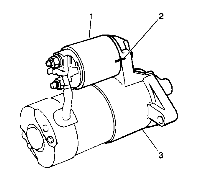
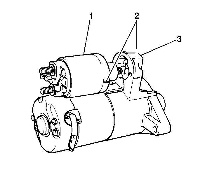
- Scribe matchmarks (2) on the solenoid and the drive housing to ensure proper solenoid installation.
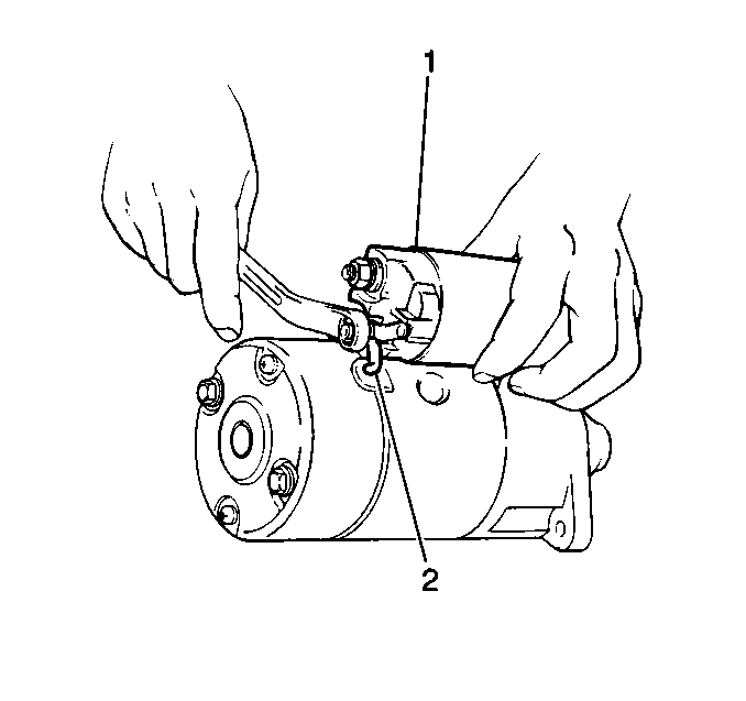
- Remove the retaining nut and the field coil lead wire (2) from the solenoid.
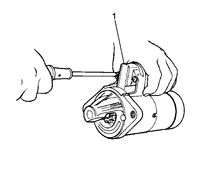
- Remove the 2 screws and the solenoid (1) from the drive housing.
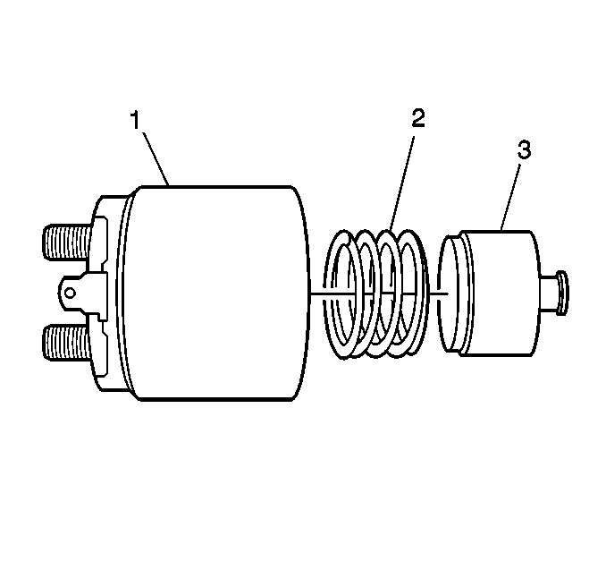
- Inspect the plunger (3) and spring for wear. Replace as necessary.
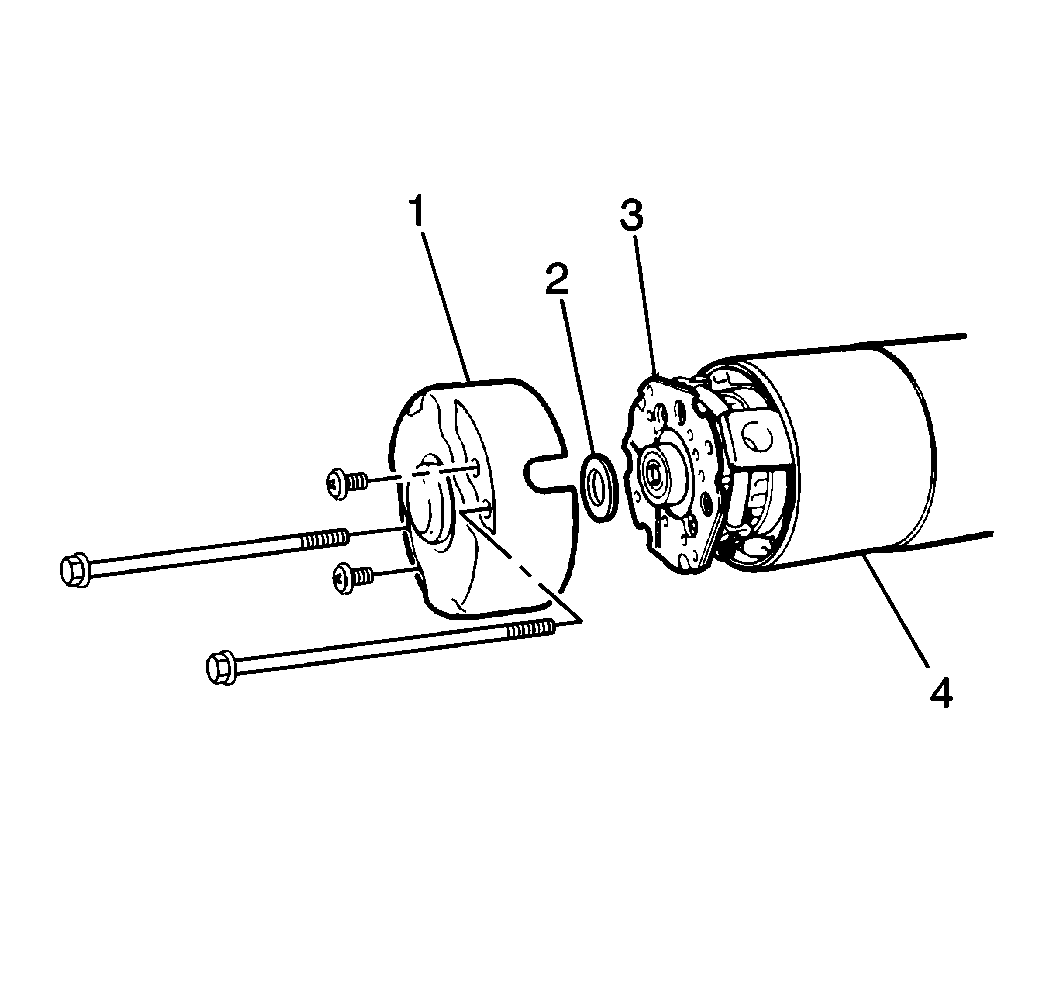
- Remove the two bolts, two screws and the commutator end cover (1) from the drive housing.
- Remove the commutator end bushing and the washers.
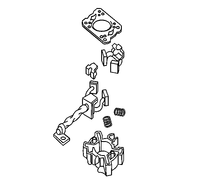
- Remove the brushholder assembly.
- Scribe matchmarks on the field frame and the drive housing to ensure proper assembly.
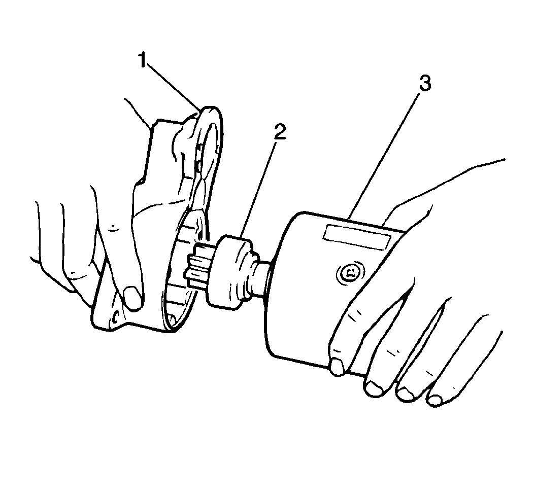
- Remove the field frame (3) from the drive housing.
- Remove the pinion drive lever from the drive housing (1).
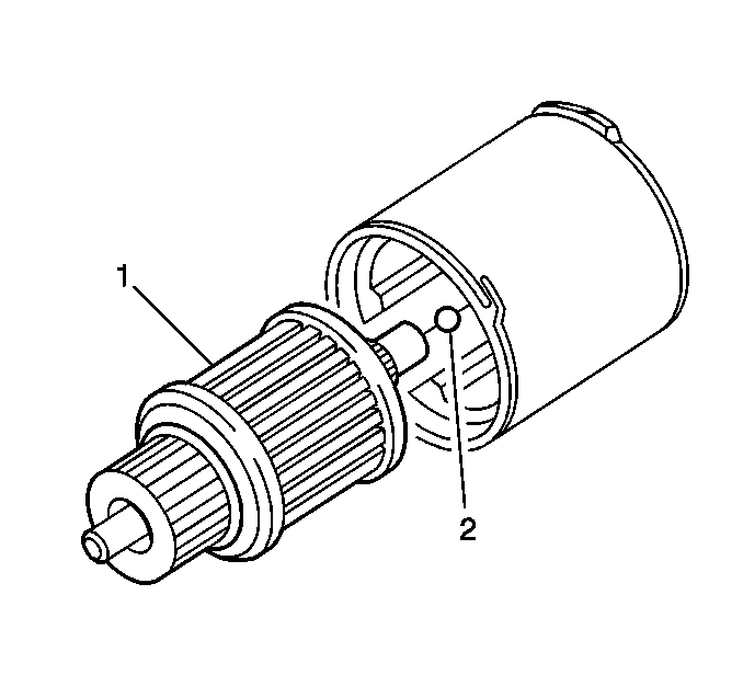
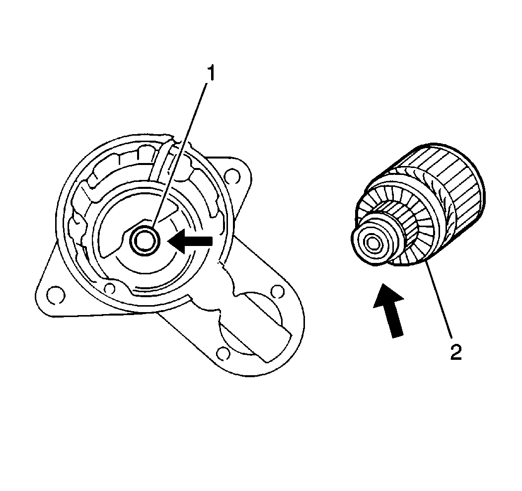
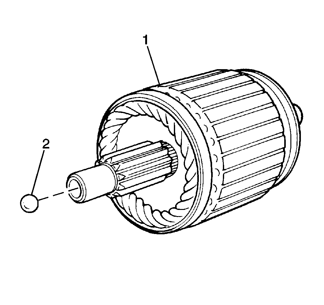
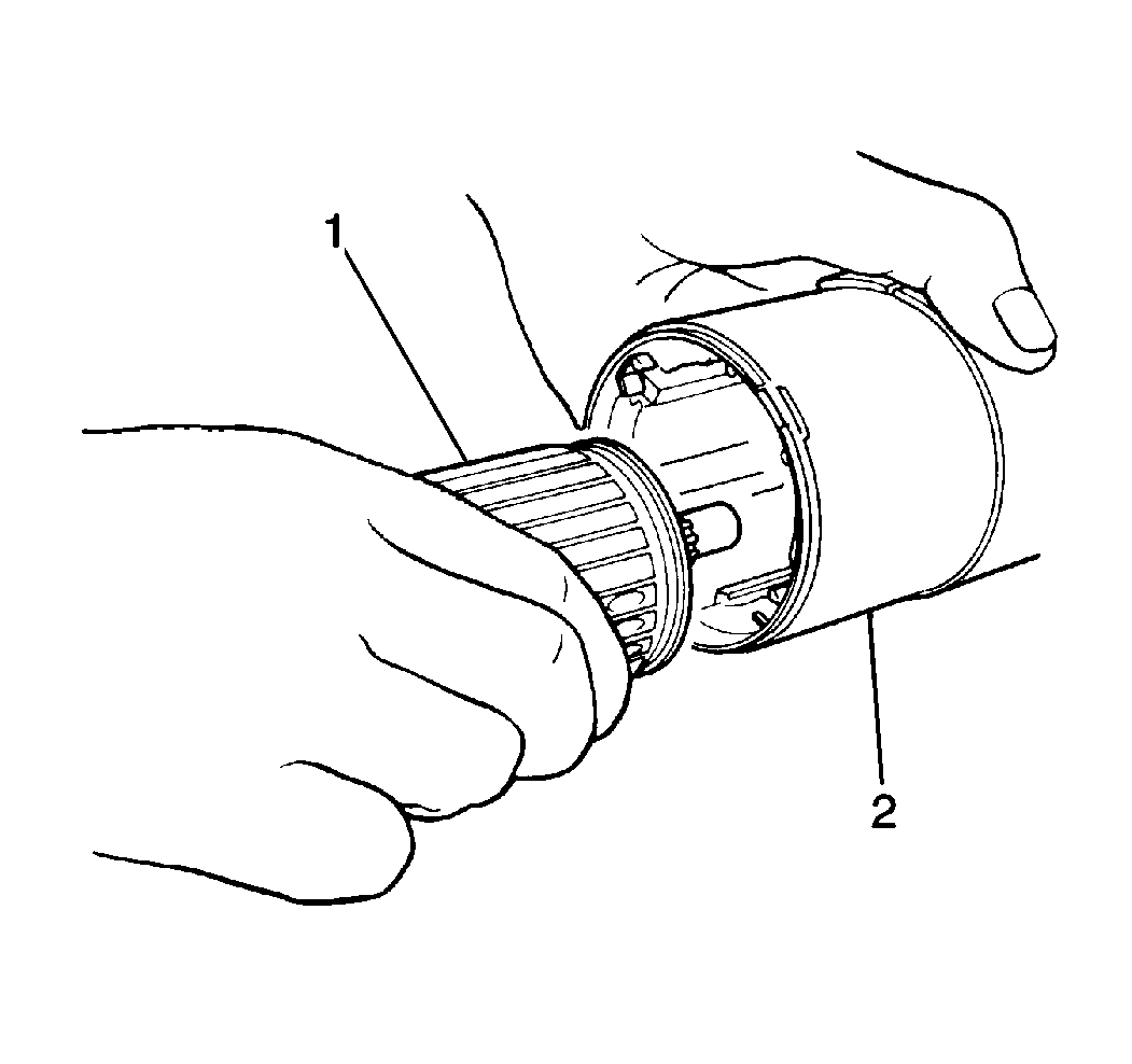
- Remove the armature (1) from the field frame. If the armature bearing (2) comes out during removal, apply Chassis Grease GM P/N 1051344 to it and reinstall.
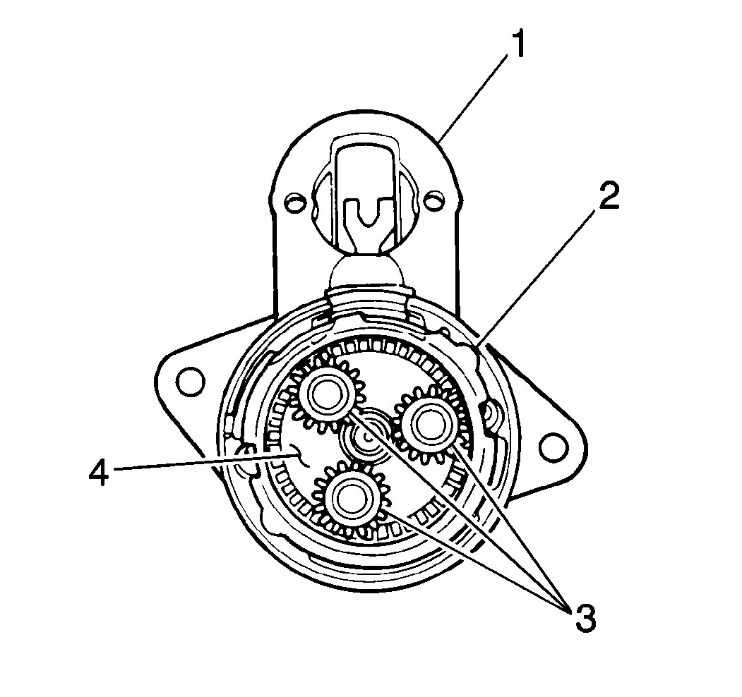
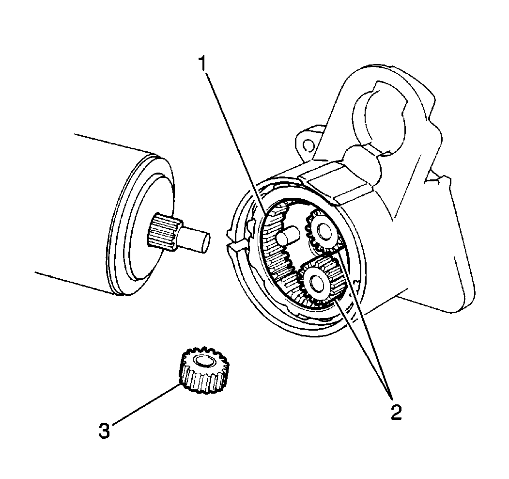
- Remove the idle gear retainer (2) and three idle gears (3) from the drive housing (1).
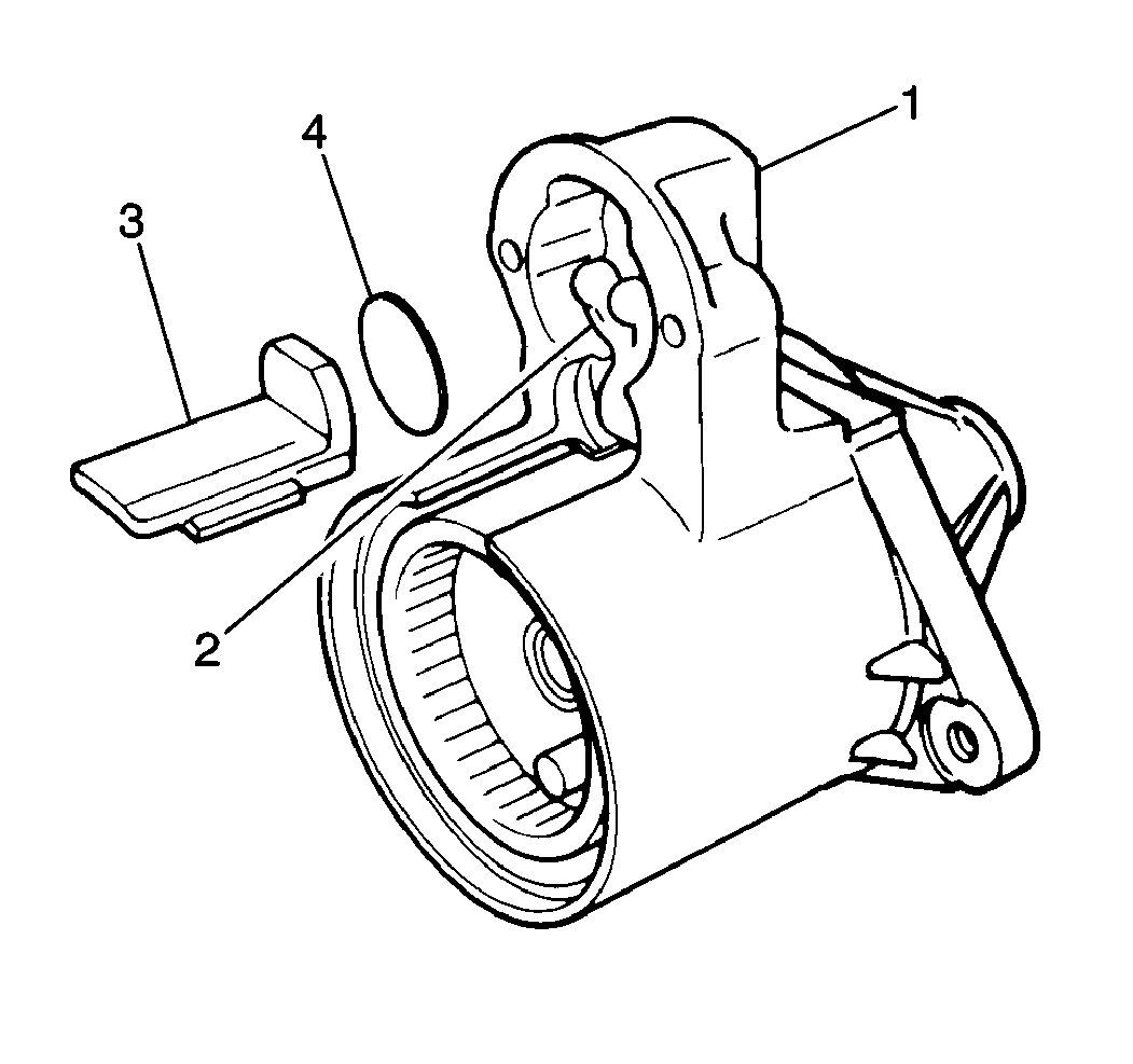
- Remove the pinion drive lever seal (3) and the plate (4) from the drive housing (1).
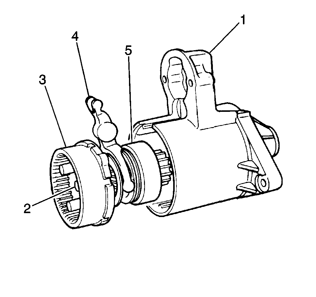
- Remove the gear shaft assembly with the pinion drive lever (4) from the drive housing (1).
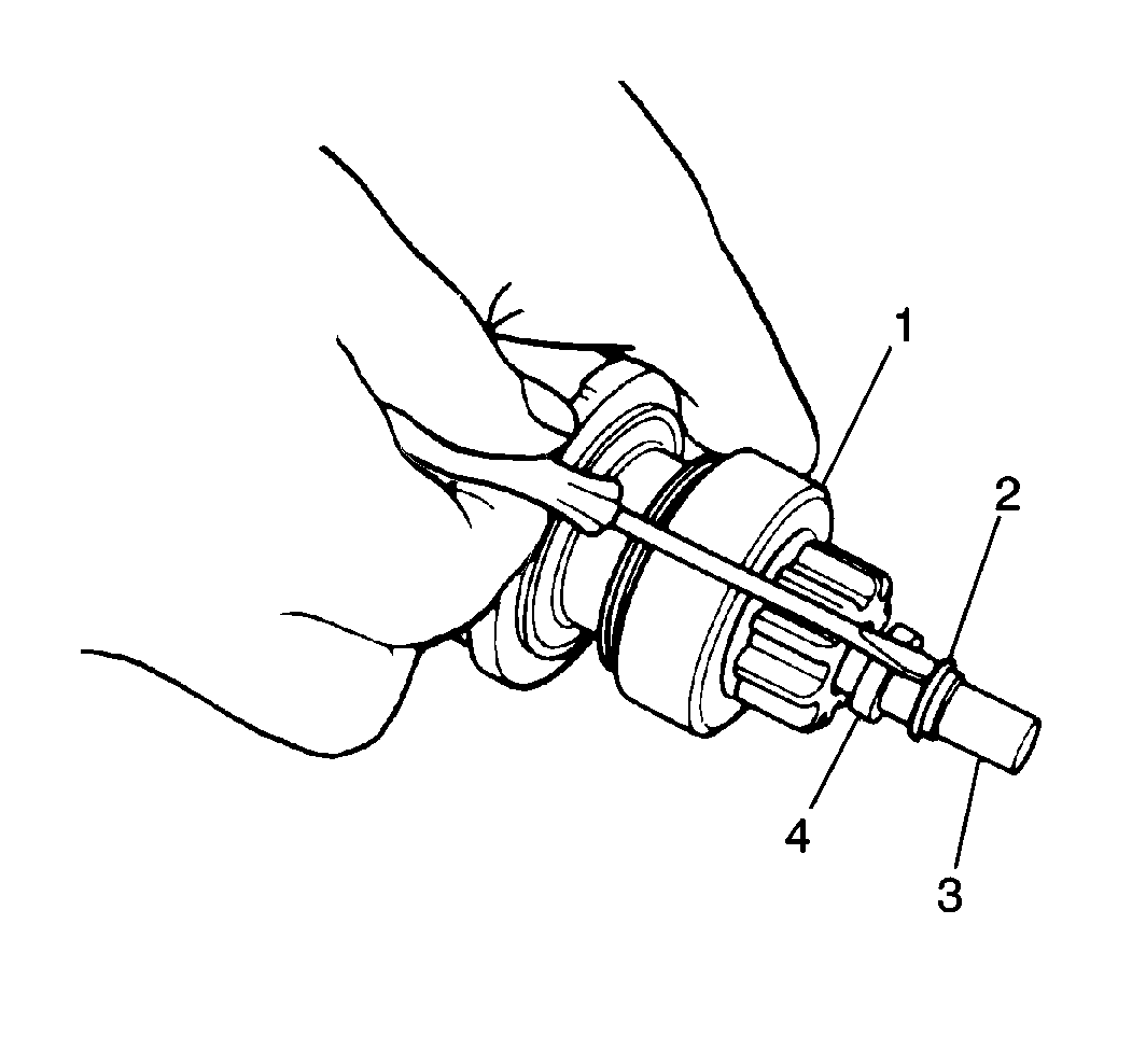
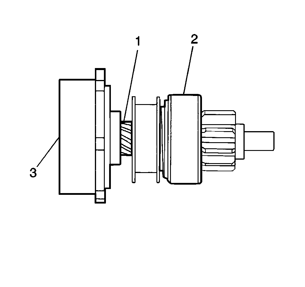
- Pull the overrunning clutch stop ring (4) towards the overrunning clutch assembly (1) and remove the overrunning clutch retaining ring (2).
- Remove the overrunning clutch stop ring and overrunning clutch assembly from the gear shaft assembly.
- Remove the internal gear from the gear shaft (3).
Important: Do not disassemble the starter solenoid. If it is found to be defective, replace the solenoid.
Cleaning, Inspection and Testing
Tools Required
| • | J 544-01 Tension Scale |
| • | J 8001 Dial Indicator |
| • | J 26900-13 Magnetic Base |
| • | J 26900-5 Vernier Caliper |
| • | J 39200 Digital Multimeter |
- Clean all starter motor parts.
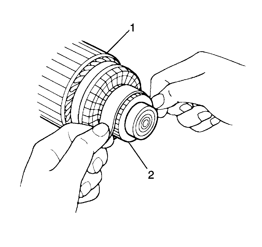
- Remove dirt and burn marks from the commutator end (2) of the armature (1) by sanding with a #300 or #400 grit sandpaper. Wipe the parts with a clean shop cloth.
- Place the armature onto a pair of V-blocks (1). Measure the commutator run-out using the J 8001 with the J 26900-13 . If the run-out exceeds the maximum, replace the armature.
- Measure the outside diameter of the commutator (2) using the J 26900-5 . If the diameter is less than the minimum, replace the armature.
- Measure the depth of the commutator insulation. If the insulation depth is less than the minimum, replace the armature.
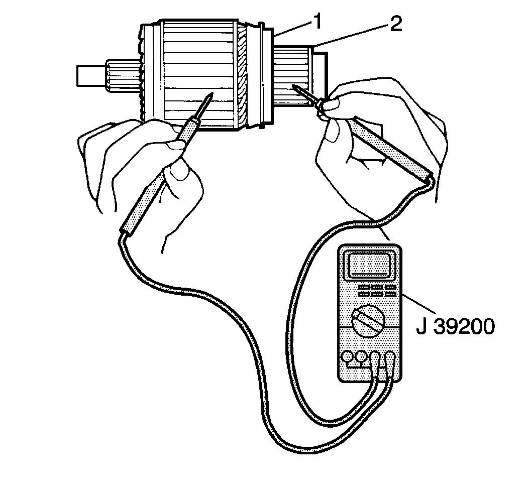
- Measure the resistance between the armature core (1) and the commutator (2) using J 39200 . If the resistance is 5.0 ohms or less, the armature is grounded . Replace the armature.
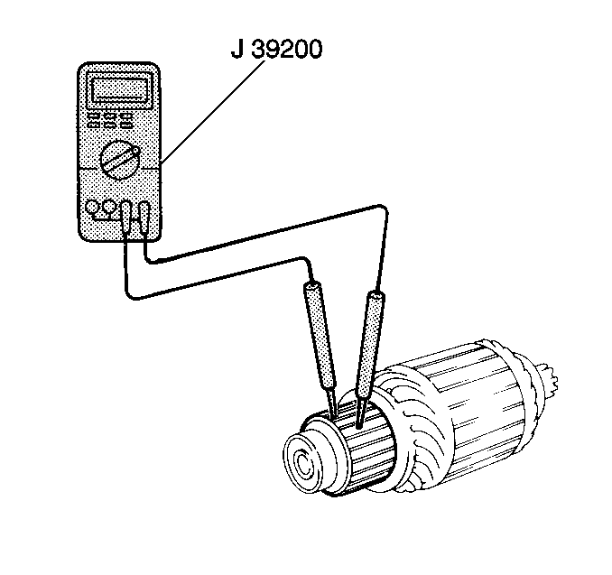
- Measure the resistance between the commutator segments using J 39200 . If resistance is greater than 5.0 ohms at any test point, an open circuit exists in the commutator. Replace the armature.
- Measure the resistance between the field coil and the field frame using the J 39200 . If the resistance is 5 ohms or less, the field windings are grounded. Replace the field frame.
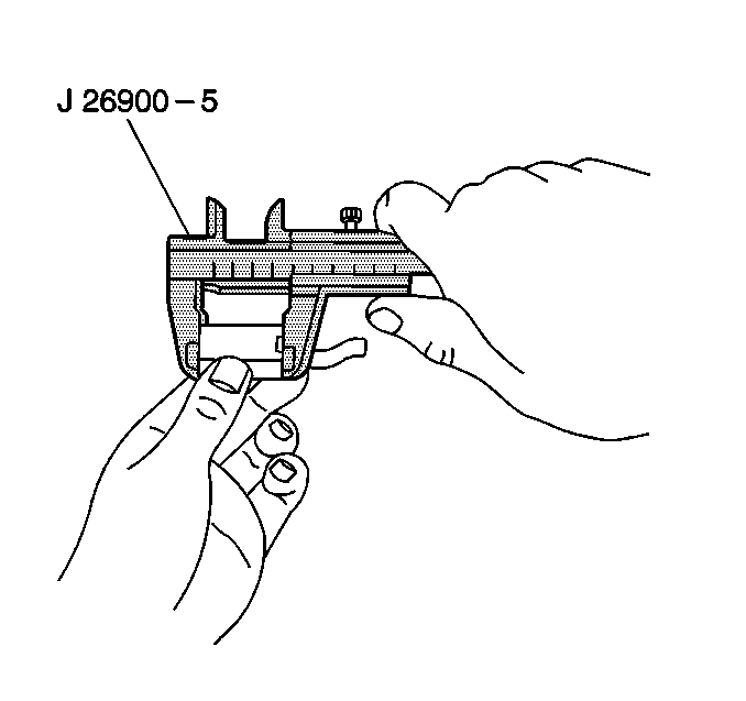
- Measure the brush length using J 26900-5 . If the brush length is less than the minimum, replace the brushholder.
- Inspect the brush holder and the insulation on the positive plates for wear. Replace the components as needed.
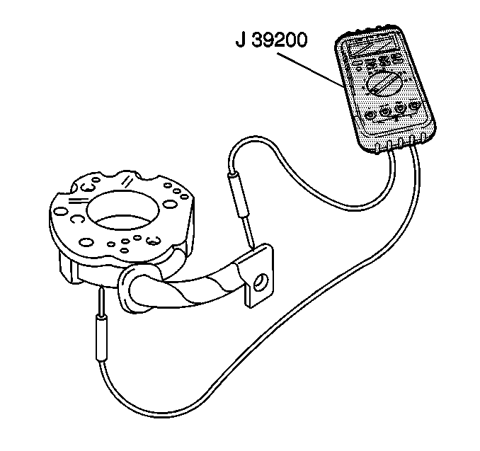
- Measure the resistance between the positive brush holder and the negative brush holder using J 39200 . If the resistance is 5.0 ohms or less, the brush holder is grounded. Replace the brush holder.
- Inspect the brush springs for corrosion or damage.
- Measure the brush spring (2) tension using J 544-01 . If the tension is less than the minimum, replace the brush spring.
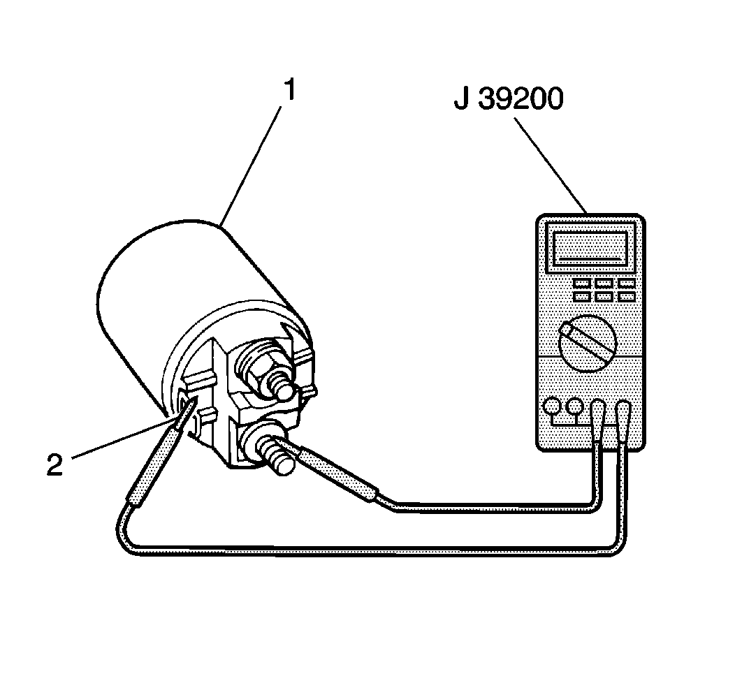
- Measure the starter solenoid pull-in coil resistance between terminal S (2) and terminal M using the J 39200 . If the resistance is greater than 5.0 ohms, the pull-in coil is open. Replace the starter solenoid.
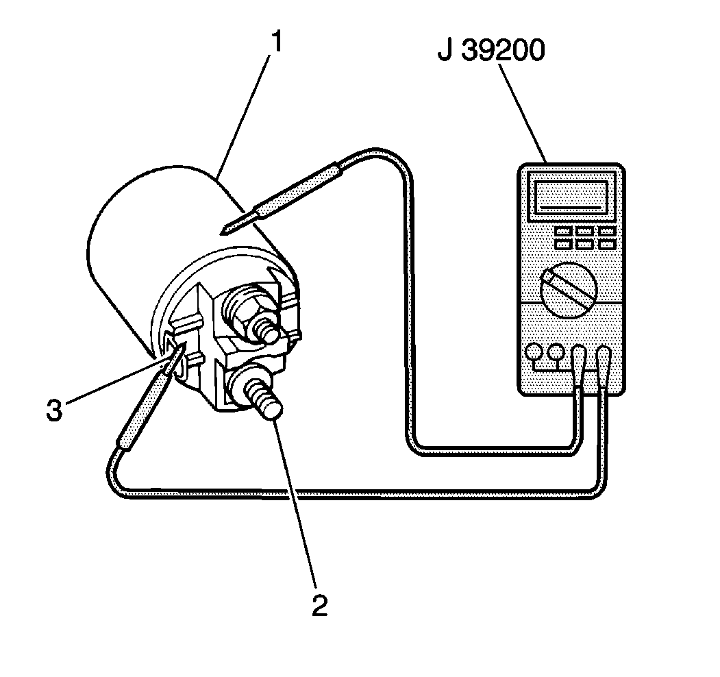
- Measure the starter solenoid hold-in coil resistance between terminal S (3) and the solenoid case (1) using the J 39200 . If the resistance is greater than 5.0 ohms, the hold-in coil is open. Replace the starter solenoid.
- Inspect the pinion drive lever (4) for wear. Replace as necessary.
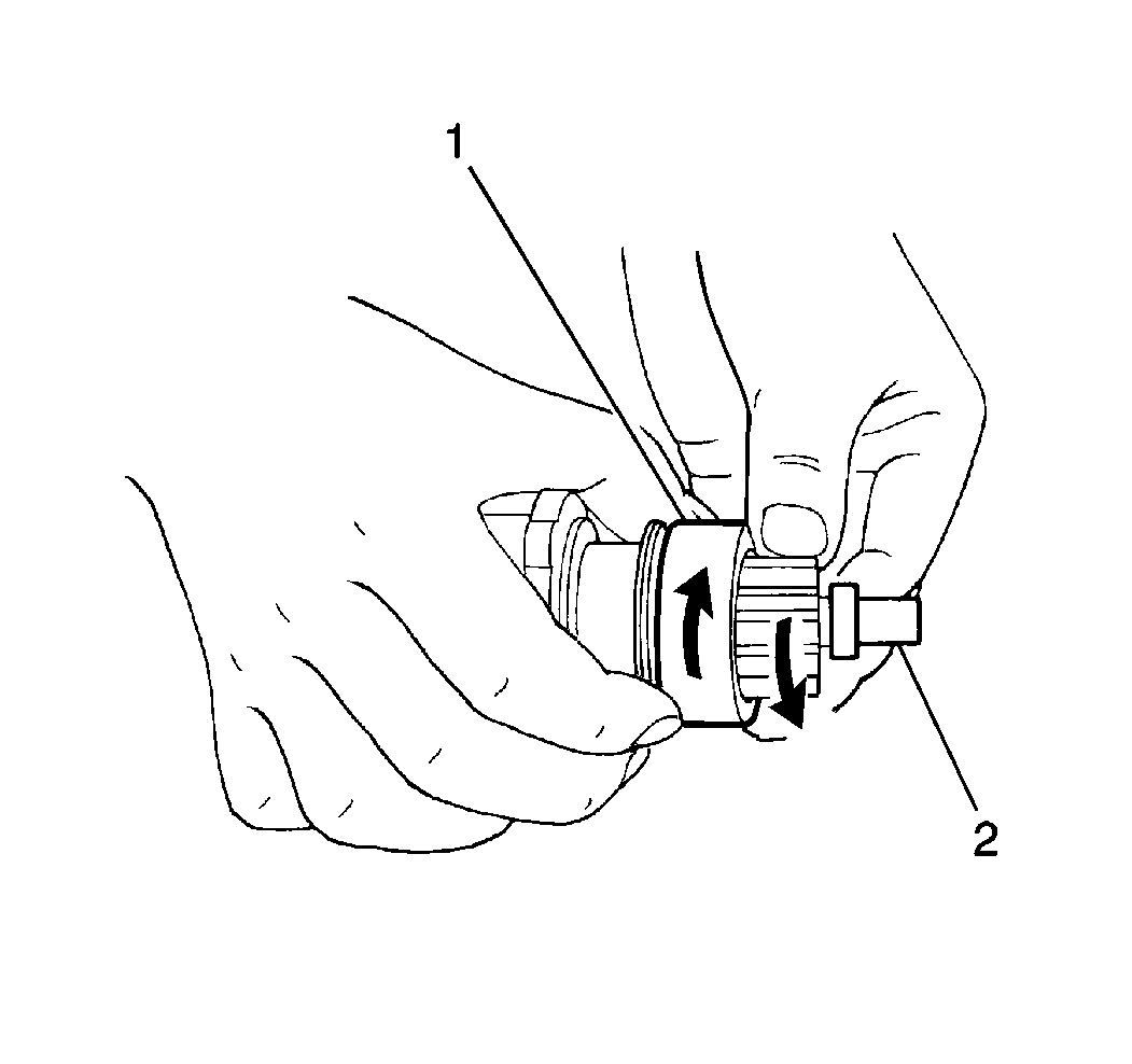
- Inspect the overrunning clutch (1) for wear, damage or other abnormal conditions. Verify that the clutch locks when turned in the drive direction, and rotates smoothly in the reverse direction. Replace as necessary.
- Inspect the overrunning clutch spline teeth (1) for wear or damage. Replace as necessary.
- Inspect the armature bushing (1) for wear and damage. Replace as necessary.
- Inspect the commutator end bushing for wear and damage. Replace as necessary.
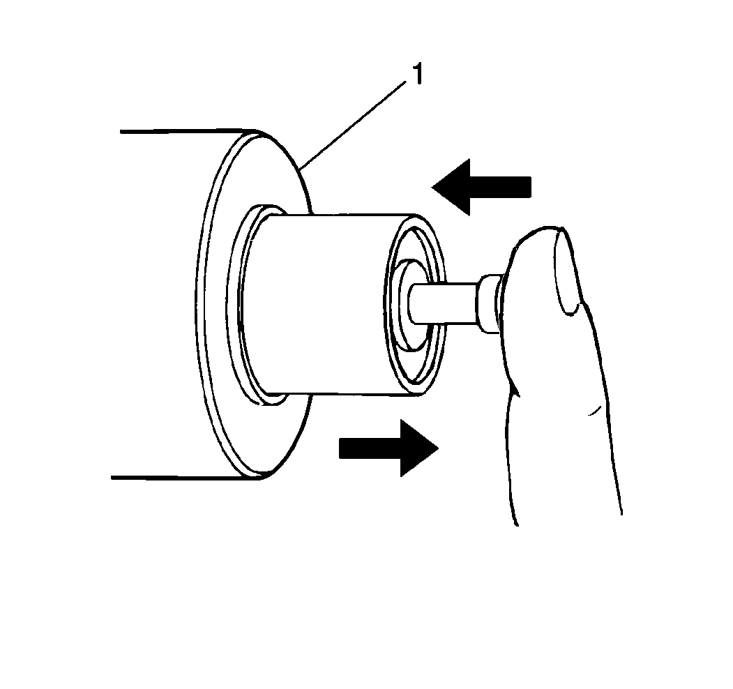
- Inspect the starter solenoid plunger operation by first pressing in the plunger and then releasing the plunger. If the plunger does not return to its original position quickly, replace the starter solenoid (1).
- Inspect the internal gear assembly (1) and idle gears (2,3) for wear, damage or other abnormal conditions. Replace as necessary.
Notice: Do not use grease dissolving solvents for cleaning the overrunning clutch or armature. Solvents dissolve the grease packed in the clutch and damage the armature and the field coil insulation.
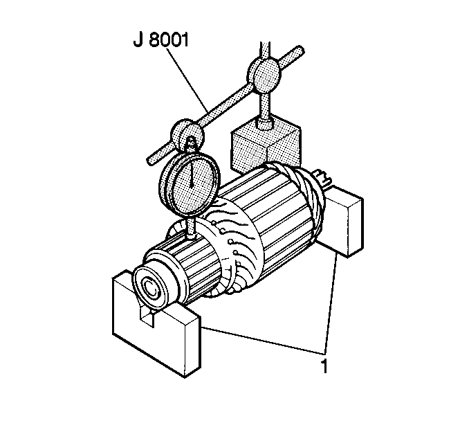
Standard Commutator Run-out
0.05 mm (0.002 in) or less
Maximum Commutator Run-out
0.40 mm (0.016 in)
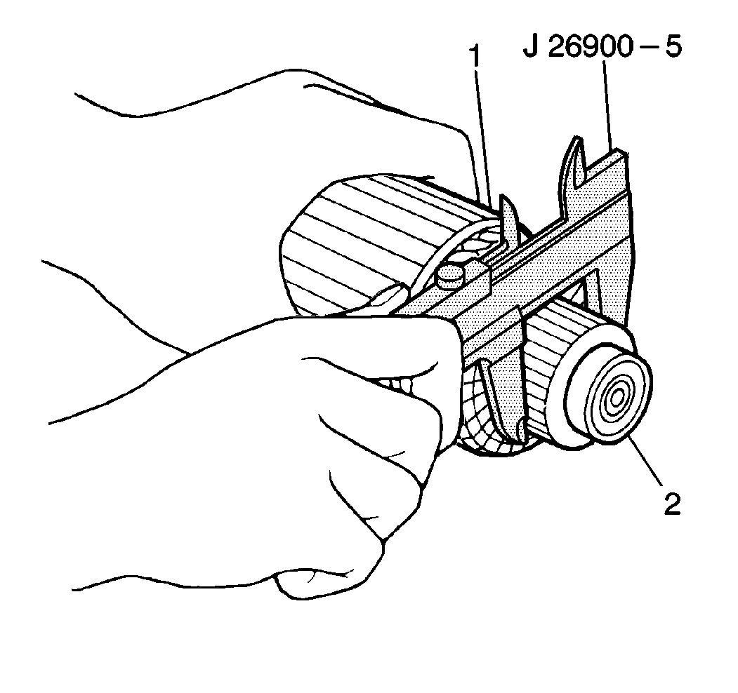
Standard Commutator Diameter
29.4 mm (1.16 in)
Minimum Commutator Diameter
28.8 mm (1.13 in)
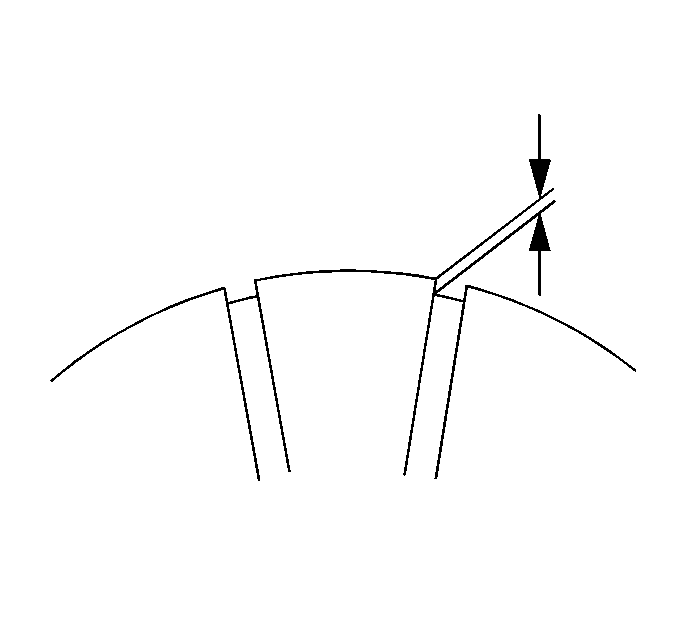
Standard Commutator Insulation Depth
0.4-0.6 mm (0.015-0.023 in)
Minimum Commutator Insulation Depth
0.2 mm (0.008 in)
Standard Brush Length
12.3 mm (0.44 in)
Minimum Brush Length
7 mm (0.28 in)
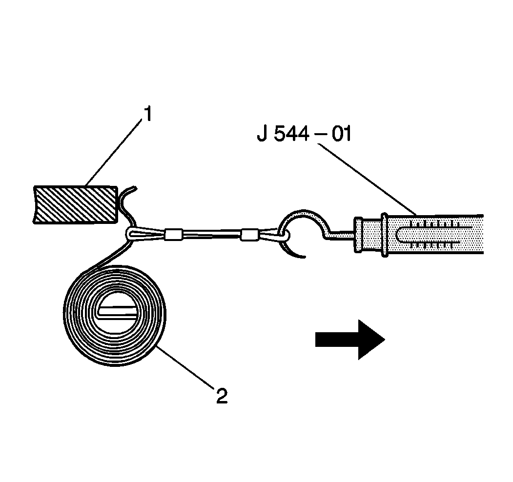
Standard Brush Spring Tension
1.9 kg (4.19 lbs)
Minimum Brush Spring Tension
0.7 kg (1.54 lbs)

Assembly Procedure
- Lightly grease the gear shaft with Lubriplate lubricant GM P/N 1050109, or the equivalent.
- Install the internal gear to the gear shaft (3).
- Install the overrunning clutch assembly and the overrunning clutch stop ring to the gear shaft assembly.
- Install the overrunning clutch retaining ring to the gear shaft assembly. Slide the overrunning clutch stop ring (4) away from the overrunning clutch assembly to cover the overrunning clutch retaining ring (2).
- Lightly grease the pinion drive lever contact points with Lubriplate lubricant GM P/N 1050109, or the equivalent.
- Install the gear shaft assembly with the pinion drive lever (4) to the drive housing (1).
- Install the pinion drive lever seal (3) and the plate (4) to the drive housing (1).
- Lightly grease the idle gears with Lubriplate lubricant GM P/N 1050109, or the equivalent.
- Install the 3 idle gears (3) to the drive housing (1). Secure with the idle gear retainer (2).
- Lightly grease the armature bearing with Lubriplate lubricant GM P/N 1050109, or the equivalent.
- Install the armature bearing (2) to the gear shaft.
- Install the armature (1) to the field frame (2).
- Install the armature bushing to the armature.
- Align the matchmarks and install the field frame (3) to the drive housing.
- Install the brushholder assembly to the commutator end.
- Install the spring washer (2) and the commutator end cover; secure with 2 bolts and 2 screws.
- Lightly grease the solenoid plunger (3) with Lubriplate lubricant GM P/N 1050109, or the equivalent.
- Install the solenoid plunger and spring.
- Install the solenoid to the drive housing, aligning the matchmarks (2).
- Install the 2 solenoid screws.
- Install the field coil lead wire (2) and the retaining nut to the solenoid.
- Install the starter to the vehicle. Refer to Starter Motor Replacement .


Important: Align the notches in the idle gear retainer with the bolt holes in the drive housing.


Notice: Use the correct fastener in the correct location. Replacement fasteners must be the correct part number for that application. Fasteners requiring replacement or fasteners requiring the use of thread locking compound or sealant are identified in the service procedure. Do not use paints, lubricants, or corrosion inhibitors on fasteners or fastener joint surfaces unless specified. These coatings affect fastener torque and joint clamping force and may damage the fastener. Use the correct tightening sequence and specifications when installing fasteners in order to avoid damage to parts and systems.
Tighten
Tighten the commutator end housing bolts to 8 N·m (71 lb in).


Notice: Use the correct fastener in the correct location. Replacement fasteners must be the correct part number for that application. Fasteners requiring replacement or fasteners requiring the use of thread locking compound or sealant are identified in the service procedure. Do not use paints, lubricants, or corrosion inhibitors on fasteners or fastener joint surfaces unless specified. These coatings affect fastener torque and joint clamping force and may damage the fastener. Use the correct tightening sequence and specifications when installing fasteners in order to avoid damage to parts and systems.
Tighten
Tighten the solenoid (1) mounting screws to 7 N·m
(62 lb in).

Tighten
Tighten the field coil lead wire nut to 10 N·m (89 lb in).
