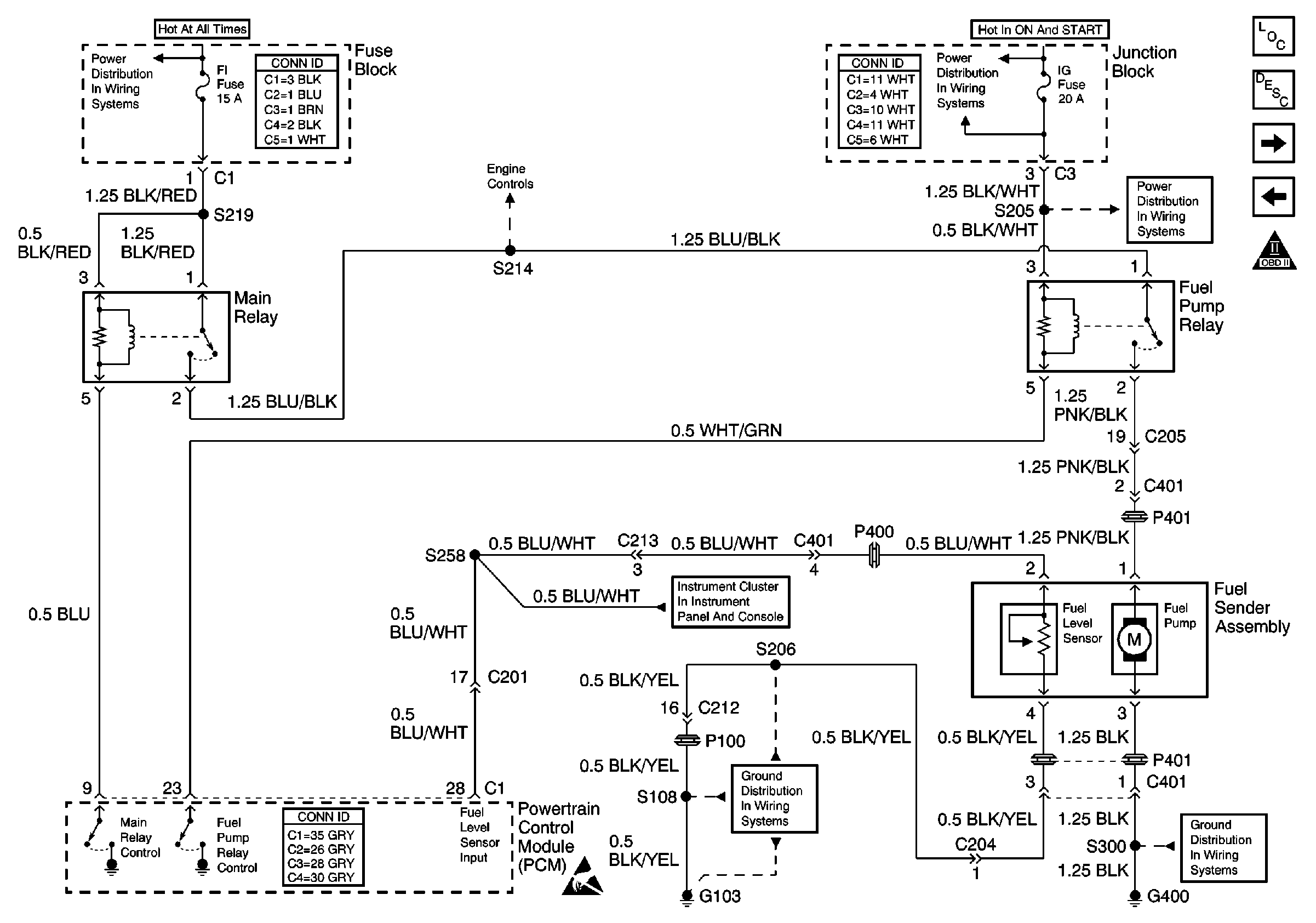
Refer to
Fuel Supply System

schematic.
Circuit Description
The powertrain control module (PCM) will energize the fuel pump relay for 3 seconds when the ignition switch is turned to the ON position. When the fuel pump relay is energized, the fuel pump will operate and pressurize the fuel system. When the engine is being cranked or is running, the PCM will receive ignition system reference pulses and will continue to energize the fuel pump relay as long as the ignition system reference pulses are detected. The fuel pump will stop after 3 seconds when the ignition is ON, unless the PCM receives ignition system reference pulses.
Diagnostic Aids
Check for any of the following conditions:
| • | Check the resistance of the fuel pump relay. The resistance across terminal 3 and terminal 5 is 79-95 ohms at 20°C (68°F). The resistance across terminal 1 and terminal 2 is infinite. |
| • | The fuel pump relay electrical contacts may be pitted or sticking. Replace the fuel pump relay if tapping gently on the relay or wiggling the relay causes a change in the relay operation. |
| • | The performance of the fuel pump relay may be affected by temperature. Check the fuel pump relay after sitting outside overnight and after running the engine 30 minutes. |
An intermittent malfunction may be caused by a fault in the fuel pump electrical circuit. Refer to Intermittent Conditions .
Use the following relay cavity table in order to locate the correct cavities to probe during diagnosis. The table layout corresponds to the cavity layout of the relay block.
Relay Cavity Identification | ||
|---|---|---|
Switch Power | ||
Switch Load | ||
Coil Power | Empty | Coil Ground |
Test Description
The numbers below refer to the step numbers in the Diagnostic Table.
-
The Powertrain OBD System Check prompts the technician to complete some basic checks, and to save the applicable freeze frame data on the scan tool. This creates an electronic copy of the data that was taken when the fault occurred. The electronic copy can then be referred to for later reference.
-
This step checks if the fuel pump relay can operate the fuel pump. The PCM turns ON the fuel pump relay for 2 seconds when the ignition switch is cycled. Use an assistant in order to operate the ignition switch while you listen for fuel pump operation.
-
This step checks the control circuit of the fuel pump relay.
-
This step determines if the coil side of the fuel pump circuit is operating correctly.
-
This step checks for an electrical fault in the fuel tank or in the fuel pump wire harness.
-
This step determines whether the switched side of the fuel pump relay is always closed.
Step | Action | Value(s) | Yes | No | ||||||
|---|---|---|---|---|---|---|---|---|---|---|
Did you perform the Powertrain On-Board Diagnostic (OBD) System Check? | -- | |||||||||
Does the fuel pump operate for approximately 2 seconds and then turn OFF? | -- | |||||||||
3 | The fuel pump electrical circuit is OK. Do you want to inspect the fuel system for the correct operating pressure? | -- | Go to Fuel System Diagnosis | Go to Intermittent Conditions | ||||||
4 | Is the fuel pump operating continuously when the ignition is ON and the engine is OFF? | -- | ||||||||
|
Important: In order to operate the fuel pump with a scan tool, the fuel level must be at least 20 percent with no DTCs set.
Does the test lamp illuminate? | -- | |||||||||
6 |
Does the test lamp illuminate? | -- | ||||||||
Is the fuel pump ON? | -- | |||||||||
8 |
Does the test lamp illuminate? | -- | ||||||||
9 |
Does the test lamp illuminate? | -- | ||||||||
Was a faulty condition found and repaired? | -- | |||||||||
11 |
Was a wiring repair necessary? | -- | ||||||||
12 | Repair the open or high resistance in the switched battery voltage supply circuit, between the fuel pump electrical connector C401 and the fuel pump relay. Refer to Wiring Repairs in Wiring Systems. Is the wiring repair complete? | -- | -- | |||||||
13 | Repair the ground connection or the open in the fuel pump ground circuit. Refer to Wiring Repairs in Wiring Systems. Is the wiring repair complete? | -- | -- | |||||||
14 |
Is the test lamp illuminated? | -- | ||||||||
15 | Repair the open or the short in the IG fuse circuit. Refer to Wiring Repairs in Wiring Systems. Is the wiring repair complete? | -- | -- | |||||||
16 |
Was a wiring repair necessary? | -- | ||||||||
Remove the fuel pump relay. Refer to Fuel Pump Relay Replacement . Is the fuel pump still operating? | -- | |||||||||
18 | Repair the short to voltage in the fuel pump supply circuit. Did you complete the repair? | -- | -- | |||||||
19 |
Did the test lamp stay illuminated for more than 3 seconds? | -- | ||||||||
20 |
Was a wiring short found and repaired? | -- | ||||||||
21 | Replace the fuel pump relay. Refer to Fuel Pump Relay Replacement . Did you complete the repair? | -- | -- | |||||||
22 | Replace the fuel pump. Refer to Fuel Tank Replacement . Did you complete the repair? | -- | -- | |||||||
23 | Replace the PCM. Refer to Powertrain Control Module Replacement/Programming . Did you complete the repair? | -- | -- | |||||||
24 | Operate the vehicle within the conditions under which the original symptom was noted. Does the system operate correctly now? | -- | System OK | Go to Diagnostic Aids |
