| Subject: | Engine Will Not Start (Install Theft Immobilizer) |
| Models: | 1999-2001 Chevrolet Tahoe (Europe Export Only) |
| With Specific Frequency Remote Entry (RPO AU8) |
| Attention: | U.S. and Canadian Dealers are not authorized to utilize this Service
Bulletin. |
This bulletin applies ONLY to the Europe Export Chevrolet Tahoe.
|
Condition
Some customers may comment on a no start condition when using the key
to unlock the doors after remote entry was not functional.
Cause
This condition may be caused by the vehicle theft deterrent system,
which requires the doors to be unlocked with the remote entry so that the
system is deactivated and the engine can be started. In high power frequency
areas (airports, hospitals and the like) the remote entry signal is not strong
enough to unlock the doors and unlocking the doors with the key will not deactivate
the theft deterrent system.
Correction
An immobilizer system, P/N 12479700, is available to enhance
the vehicle's theft deterrent characteristics. Install the immobilizer system
using the procedure listed below.
- Disconnect the negative terminal of the vehicle battery.
- Remove the knee bolster. Refer to the Instrument Panel, Gauges,
and Console sub-section of the Service Manual.
- Remove the instrument panel (IP) cluster bezel. Refer to the Instrument
Panel, Gauges, and Console sub-section of the Service Manual.
- Remove the radio. Refer to the Entertainment sub-section of the
Service Manual.
- Remove the IP upper trim pad. Refer to the Instrument Panel, Gauges,
and Console sub-section of the Service Manual.

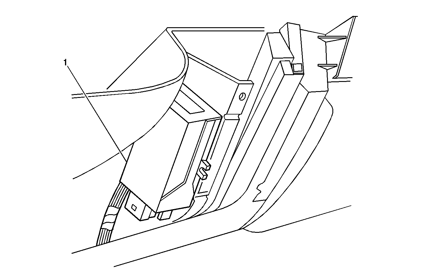
- Attach Velcro® to the back of the
immobilizer module (1) and install onto the IP support. Attach the
module on the support with the connectors facing towards the floor of the
vehicle.
- To establish the power connection to the immobilizer, follow these
steps:
| 7.1. | Locate connector C1 of the body control module (BCM). |
| 7.2. | Locate terminal A2 on the connector. This wire is the positive
battery circuit (1140) and is orange in color. |
| 7.3. | Strip a section of the insulation from this wire approximately
80 mm (3.15 in) from its termination at the connector. |
| 7.4. | Take the wire from the immobilizer with the red identifier and
cut the wire to length. |
| 7.5. | Strip the immobilizer wire and connect the wire to the section
of circuit 1140. |
- To establish a ground connection to the immobilizer, follow these
steps:
| 8.1. | Locate connector C1 of the BCM. |
| 8.2. | Locate terminal A1 on the connector. This wire is a ground
circuit (1850) and is black in color. |
| 8.3. | Strip a section of the insulation from this wire approximately
80 mm (3.15 in) from its termination at the connector. |
| 8.4. | Take the wire from the immobilizer with the no color identifier
and cut the wire to length. |
| 8.5. | Strip the immobilizer wire and connect the wire to the section
of circuit 1850. |
- To establish the chassis ground connection, follow these steps:
| 9.1. | Locate connector C1 of the BCM. |
| 9.2. | Locate terminal B1 on the connector. This wire is a ground
circuit (1850) and is black in color. |
| 9.3. | Strip a section of the insulation from this wire approximately
80 mm (3.15 in) from its termination at the connector. |
| 9.4. | Take the wire from the immobilizer with the text identifier "CH
CH" and cut the wire to length. |
| 9.5. | Strip the immobilizer wire and connect the wire to the section
of circuit 1850. |
- To establish an ignition Input connection to the immobilizer,
follow these steps:
| 10.1. | Locate connector C1 of the BCM. |
| 10.2. | Locate terminal B2 on the connector. This wire is the ignition
positive voltage circuit (39) and is pink in color. |
| 10.3. | Strip a section of the insulation from this wire approximately
80 mm (3.15 in) from its termination at the connector. |
| 10.4. | Take the wire from the immobilizer with the orange identifier
and cut the wire to length. |
| 10.5. | Strip the immobilizer wire and connect the wire to the section
of circuit 39. |
- For starter relay circuit Interruption, follow these steps:
| 11.1. | Locate the left hand IP bussed electrical center fuse block connector.
Loosen the bolt and disconnect from the fuse block. |
| 11.2. | Locate terminal D5 on the connector. This wire is the starter
relay circuit (2806) and is light green in color. |
| 11.3. | Cut this wire approximately 80 mm (3.15 in) from
its termination at the connector and strip the ends of the wires. |
| 11.4. | Take the wire from the immobilizer with the brown/white identifier
and cut the wire to length. |
| 11.5. | Strip the immobilizer wire and connect the wire to the light green
wire coming from the fuse block connector. |
| 11.6. | Take the wire from the immobilizer with the brown identifier and
cut the wire to length. |
| 11.7. | Strip the immobilizer wire and connect the wire to the other wire
of circuit 2086. |
- For fuel pump relay circuit Interruption, follow these steps:

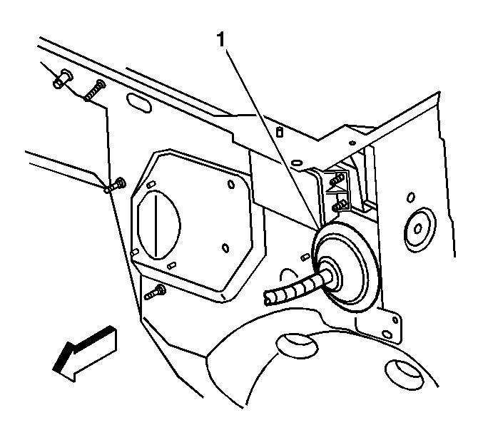
| 12.1. | Route the immobilizer wires with the
green/white and green identifiers through a gap in the pas through (1)
on the dash panel located just forward of the left hand IP bussed electrical
center fuse block to the engine compartment. |
| 12.2. | From the engine compartment, pull these wires to the PCM. |
| 12.3. | If the vehicle has a 4.3L engine, follow these steps: |
| • | Locate connector C4 on the PCM. |
| • | Locate terminal 1 on the connector. This wire is the fuel
pump relay circuit (465) and is dark green/white in color. |
| • | Cut this wire approximately 80 mm (3.15 in) from
its termination at the connector and strip the ends of the wires. |
| • | Take the wire from the immobilizer with the green/white identifier
and cut the wire to length. |
| • | Strip the immobilizer wire and connect the wire to the dark green/white
wire coming from the PCM connector. Use the supplied splice connector and
shrink-wrap for protection. |
| • | Take the wire from the immobilizer with the green identifier and
cut the wire to length. |
| • | Strip the immobilizer wire and connect the wire to the other wire
of circuit 465. Use the supplied splice connector and shrink-wrap for
protection. |
| 12.4. | If the vehicle has a 4.8L, 5.3L, or a 6.0L engine, follow these
steps: |
| • | Locate connector C2 on the PCM. |
| • | Locate terminal 9 on the connector. This wire is the fuel
pump relay circuit (465) and is dark green/white in color. |
| • | Cut this wire approximately 80 mm (3.15 in) from
its termination at the connector and strip the ends of the wires. |
| • | Take the wire from the immobilizer with the green/white identifier
and cut the wire to length. |
| • | Strip the immobilizer wire and connect the wire to the dark green/white
wire coming from the PCM connector. Use the supplied splice connector and
shrink-wrap for protection. |
| • | Take the wire from the immobilizer with the green identifier and
cut the wire to length. |
| • | Strip the immobilizer wire and connect the wire to the other wire
of circuit 465. Use the supplied splice connector and shrink-wrap for
protection. |
- For Security LED installation, follow these steps:
| 13.1. | Remove the buzzer from the LED harness. Cut the buzzer wires close
to the LED/buzzer connector. The buzzer is not needed for this application. |

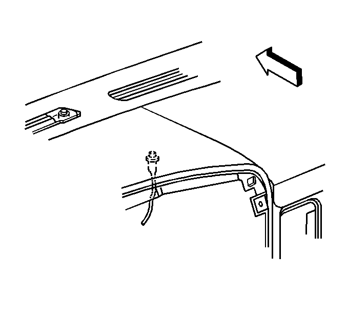
| 13.2. | Mark the location of the LED on the IP
upper trim pad. Inline with the light sensor, measure approximately 150 mm
(6 in) rearward and mark the location. |
| 13.3. | Drill hole using an 8 mm (0.31 in) (5/16 in)
bit. |
| 13.4. | Remove the LED from the housing. Install the housing to the IP
upper trim pad. Push the LED firmly into the housing. |
| 13.5. | Install the IP upper trim pad. Refer to the Instrument Panel,
Gauges, and Console sub-section of the Service Manual. |
| 13.6. | Route the LED harness to the immobilizer module and insert the
connector. |
- For door jam connection to the immobilizer, follow these steps:
| 14.1. | Locate connector C3 of the BCM. |
| 14.2. | Locate terminal B4 on the connector. This wire is the driver's
door jam switch circuit (126) and is tan in color. |
| 14.3. | Strip a section of the insulation from this wire approximately
80 mm (3.15 in) from its termination at the connector. |
| 14.4. | Route the white/black wire from the security LED harness to the
BCM and cut to length. |
| 14.5. | Strip the LED wire and connect the wire to the section of circuit 126. |

Important: Location of the reader/exciter coil is critical to proper operation
of the immobilizer. Follow the instructions to properly install the reader/exciter
coil.
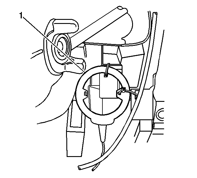
- For reader/exciter coil installation, follow these steps:
| 15.1. | Drill a hole in the IP cluster housing at the lower right tab
using an 8 mm (0.31 in) (5/16 in) bit. |
| 15.2. | Install the reader/exciter coil (1) to the IP. Attach using
tie straps at the previously drilled location and at the IP cluster bezel
retaining slot in the carrier. |
| 15.3. | Route the reader/exciter coil harness to the immobilizer module
and insert the connector. |
| 15.4. | Wrap up excess slack from the reader/exciter coil harness and
tie strap to the IP. |
- Solder and tape all connections.
- Install the transponder(s) to the customer's key ring(s).
- Install the radio. Refer to the Entertainment sub-section of the
Service Manual.
- Install the IP cluster bezel. Refer to the Instrument Panel, Gauges,
and Console sub-section of the Service Manual.
- Install the knee bolster. Refer to the Instrument Panel, Gauges,
and Console sub-section of the Service Manual.
- Connect the negative terminal of the vehicle battery.
- Reflash the BCM with the theft calibration software using the
Tech 2®.
Parts Information
Part Number
| Description
|
12479700
| Kit, Theft Immobilizer
|
Parts are currently available from GMSPO.
Warranty Information
For vehicles repaired under warranty, use:
Labor Operation
| Description
| Labor Time
|
R4802
| Immobilizer Kit Installation
| 1.6 hrs
|


