Removal Procedure
- Disconnect the negative battery cable. Refer to
Battery Negative Cable Disconnection and Connection
in Engine Electrical.
- Disable the SIR system. Refer to
Disabling the SIR System
in SIR.
- Remove the body hinge pillar trim panels. Refer to
Body Hinge Pillar Trim Panel Replacement
in Interior Trim.
- Remove the IP drivers knee bolster reinforcement. Refer to
Knee Bolster Replacement
.
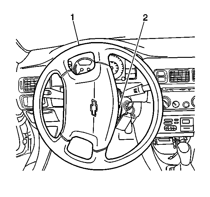
Important: It is not necessary to remove the steering wheel to access the lower
trim cover screws. The screws can be easily accessed by rotating the steering
wheel.
- Remove the following components from the steering column:
| • | The lower trim cover screw |
| • | The 2 lower trim cover screws (2) which are located beneath
the steering wheel (1). |
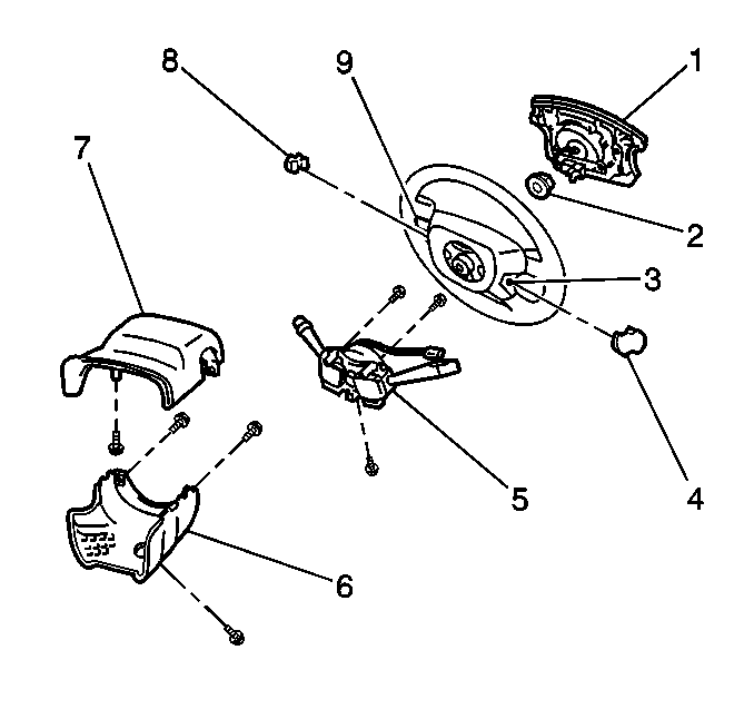
- Remove the steering column
lower trim cover (6).
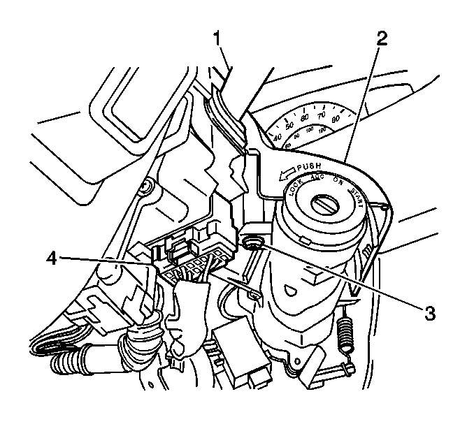
- Remove the following components
from the steering column:
| • | The steering column upper trim cover screw (3) |
| • | The steering column upper trim cover (2) |
Important: DO NOT remove the following components from the steering column when
removing the column in order to gain the necessary access to remove the instrument
panel assembly:
| • | The turn signal and headlamp and windshield washer switch with the
inflatable restraint coil assembly |
| • | The ignition lock cylinder case with the ignition lock cylinder and
the ignition switch |
- Remove the steering column. Refer to
Steering Column Replacement
in Steering Wheel and Column - Standard or
Steering Column Replacement
.
- Remove the instrument cluster assembly. Refer to
Instrument Cluster Replacement
.
- Remove the IP accessory center trim plate. Refer to
Instrument Panel Center Trim Panel Replacement
.
- Remove the radio. Refer to
Radio Replacement
in Entertainment.
- Remove the instrument panel compartment. Refer to
Instrument Panel Compartment Replacement
.
- Remove the front floor rear console. Refer to
Rear Floor Console Replacement
.
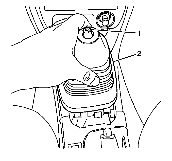
- Remove the manual transaxle
control lever boot (2) and bezel from the front floor front console,
if equipped.
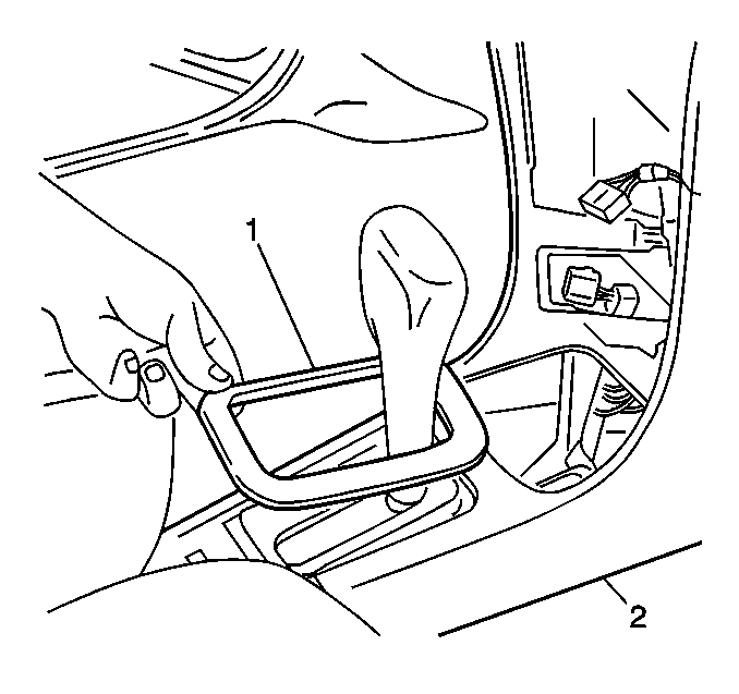
- Remove the automatic transaxle
control opening cover bezel (1) from the front console by gently prying
the rear of the bezel in order to release the tabs, if equipped.
- Remove the following components from the vehicle:
| • | The front floor front console (2) |
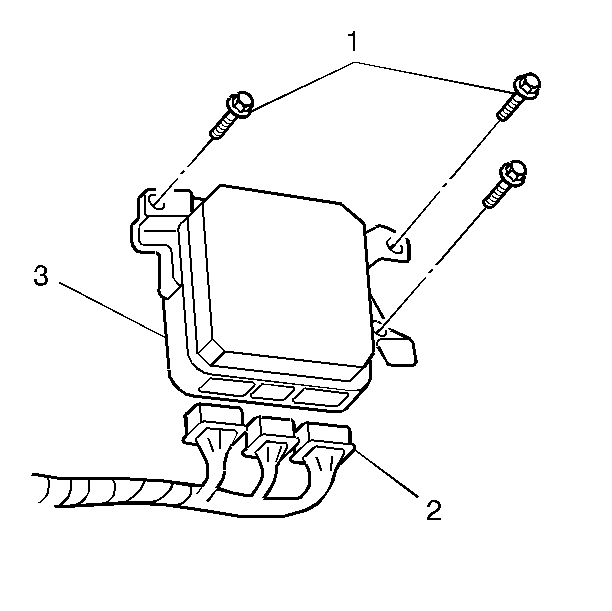
- Remove the 3 mounting
bolts (1) which secure the powertrain control module.
- Disconnect the 3 powertrain control module electrical connectors
(2).
- Remove the powertrain control module (3) from the vehicle.
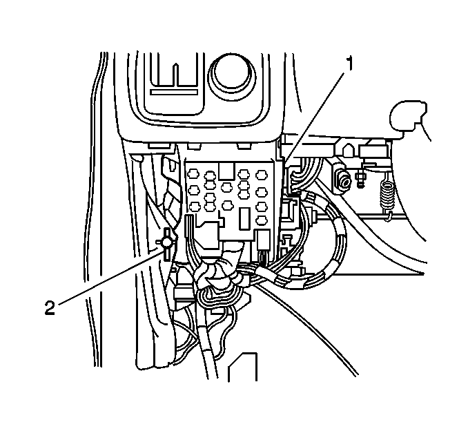
- Remove the screw (2)
which secures Junction Block #2 (1) to the instrument panel. Reposition
the block as necessary.
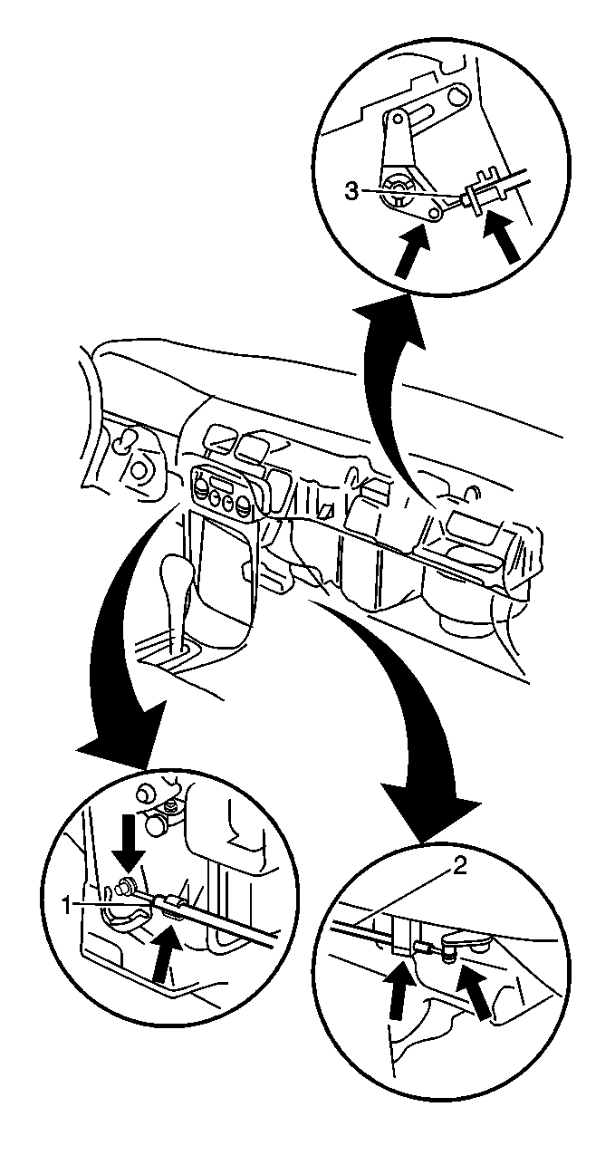
- Remove the following control
cables from the heater case assembly:
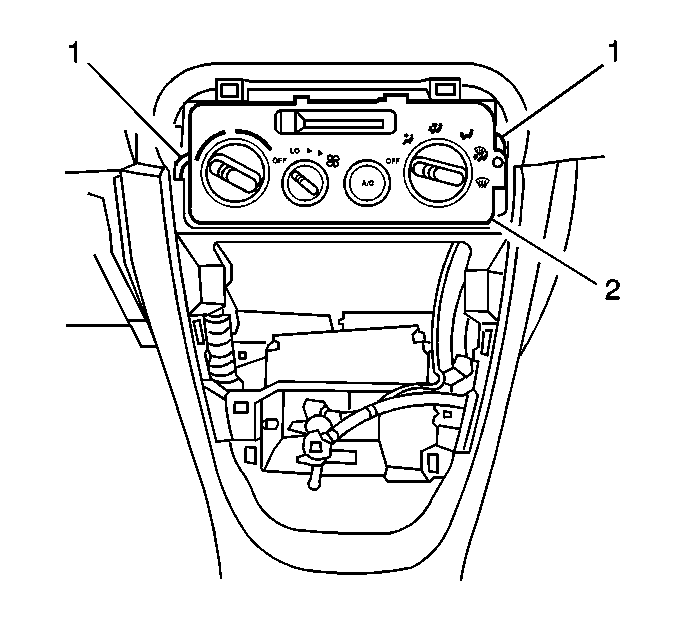
- Remove the 2 screws
(1) which secure the heater control assembly (2).
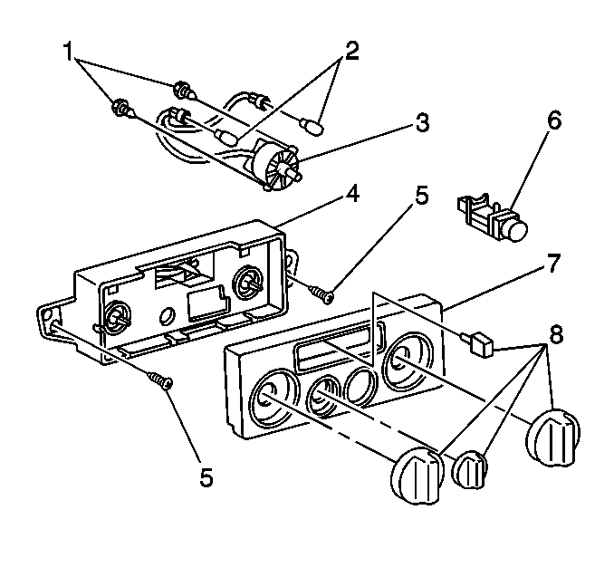
- Disconnect the following
connectors from the heater control assembly:
| • | The blower motor switch (2) |
- Remove the heater control assembly with the control cables attached
from the vehicle.
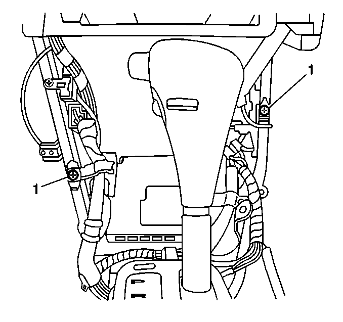
- Remove the following components
from the IP center support braces:
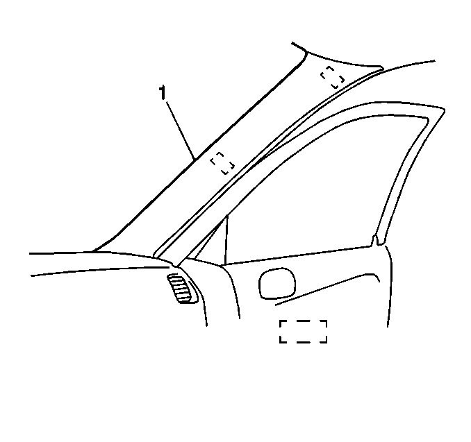
- Unclip and remove the
windshield side garnish moldings (1).
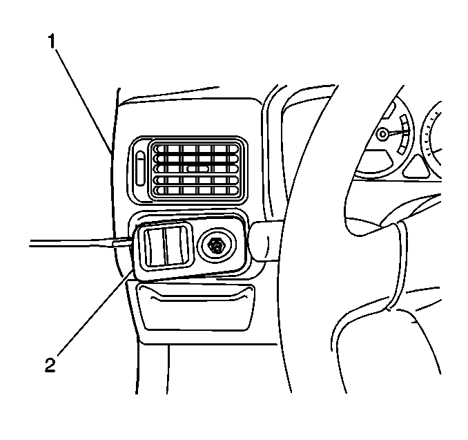
- Using a taped flat bladed
tool, gently pry and release the 4 clips around the IP lamp dimmer/outside
rearview mirror switch trim plate (2).
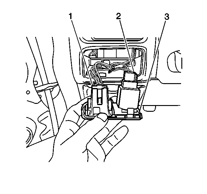
- Disconnect the following
electrical connectors:
| • | The outside rearview mirror switch (1), if equipped |
- Remove the IP lamp dimmer/outside rearview mirror switch assembly
(3) from the vehicle.
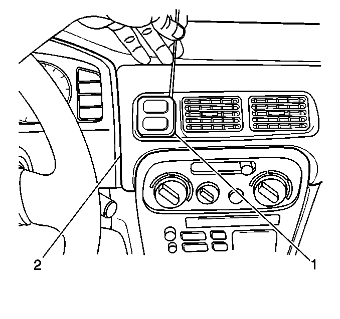
- Using a taped flat bladed
tool, gently pry and release the 3 clips around the IP hazard warning/rear
defogger switch trim plate (1).
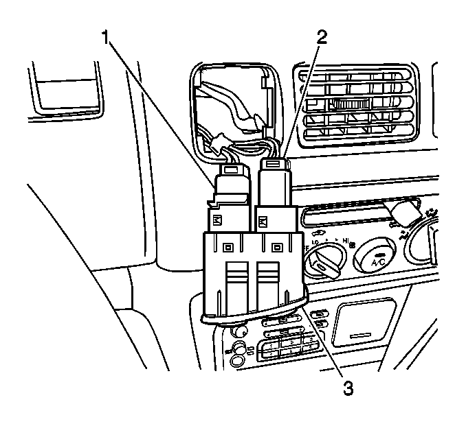
- Disconnect the following
electrical connectors:
| • | The rear defogger switch (1), if equipped |
| • | The hazard warning switch (2) |
- Remove the rear defogger switch/hazard warning switch assembly
(3) from the vehicle.
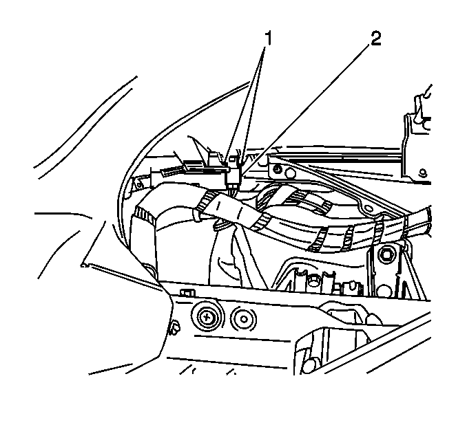
- Disconnect the ambient
light sensor electrical connector (2).
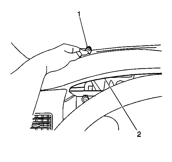
- Remove the ambient light
sensor (1) from the instrument panel assembly (2).
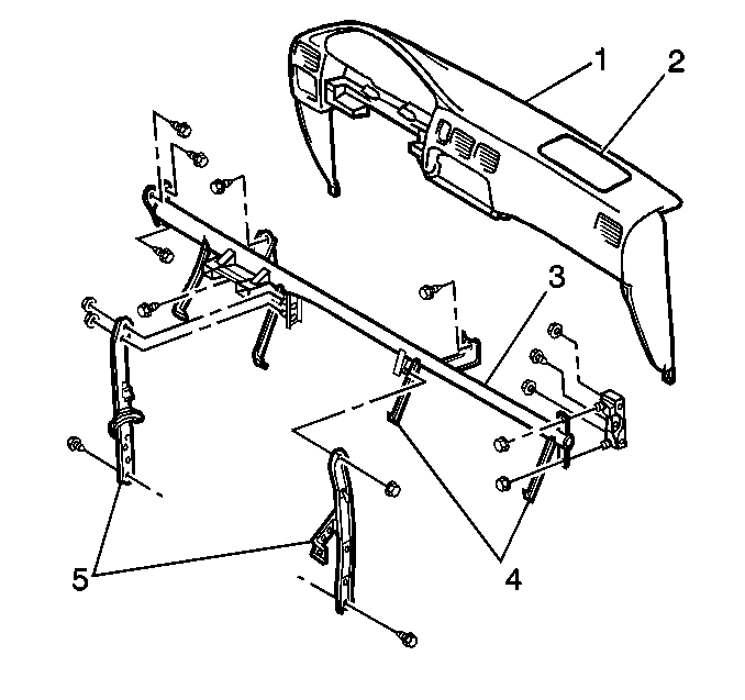
- Remove the following components
from the IP assembly (1):
| • | The inflatable restraint IP module (2) |
- Remove the following components:
| • | The IP compartment reinforcements (4) |
- Remove the IP compartment door lock striker bracket screw.
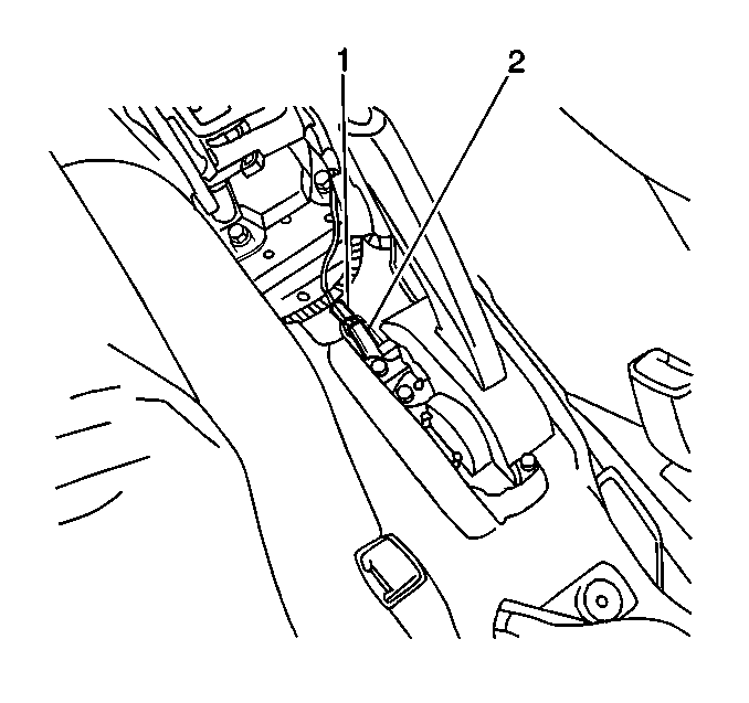
- Disconnect the park brake
switch electrical connector (1).
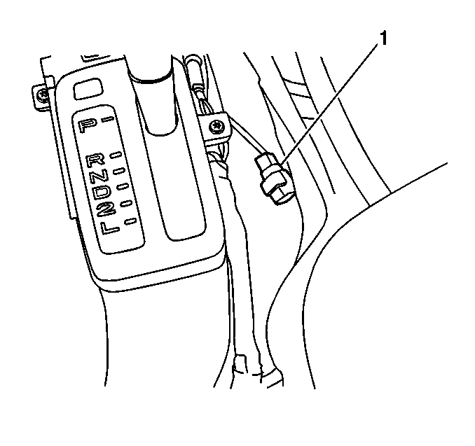
- Disconnect the oxygen
sensor (H02S2) electrical connector (1).
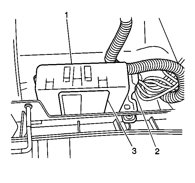
- Disconnect the daytime
running lamp control module electrical connector (2).

- Disconnect the 8 connectors
from Junction Block #2 (1).
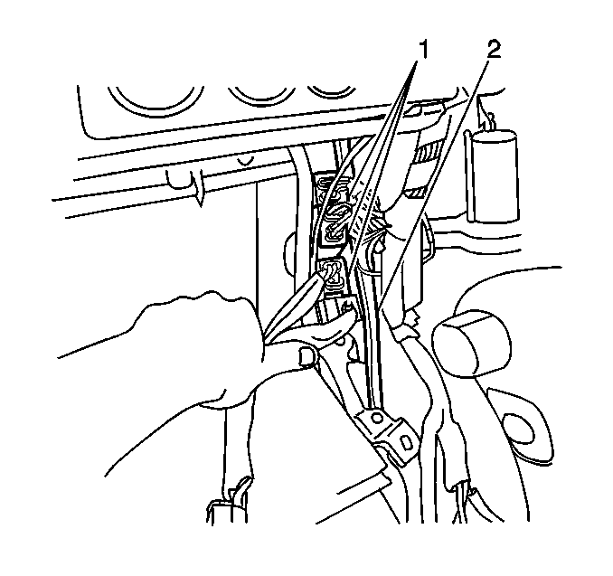
- Disconnect the connectors
(1) at the right IP center support brace (2).
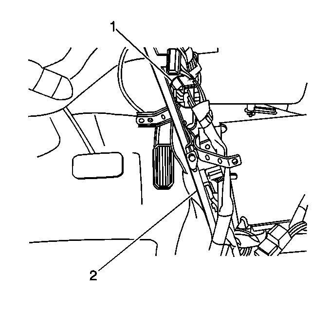
- Disconnect the connectors
(1) at the left IP center support brace (2).
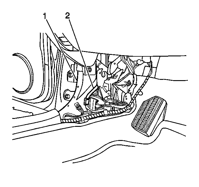
- Disconnect the 3 connectors
which are located in the connector cavity (2) in the left body hinge pillar
(1).
- Disconnect the following electrical connectors:
| • | The automatic transaxle shift lock control module |
| • | The shift lock park switch |
| • | The 4 connectors from Junction Block #1 |
- Remove the I/P wiring harness from all the necessary wire harness
retainers.
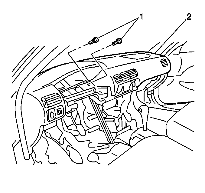
- Remove the 2 screws
(1) which secure the instrument panel assembly (2) to the instrument panel
reinforcement.
- Remove the instrument panel assembly from the vehicle by lifting
up on and pulling the assembly rearward, disengaging the 5 clips.
Installation Procedure

- Install the instrument
panel assembly (2) to the vehicle. Ensure that the retaining clips are fully
engaged. Secure the assembly to the instrument panel reinforcement
with the 2 screws (1).
- Route and install the IP wiring harness to the retainers.

- Connect the park brake
switch electrical connector (1).

- Connect the oxygen sensor
(H02S2) electrical connector (1).

- Connect the daytime running
lamp control module electrical connector (2).

- Connect the 8 connectors
to Junction Block #2 (1).

- Connect the connectors
(1) at the right IP center support brace (2).

- Connect the connectors
(1) at the left IP center support brace (2).

- Connect the 3 connectors
which are located in the connector cavity (2) in the left body hinge pillar
(1).
- Connect the following electrical connectors:
| • | The automatic transaxle shift lock control module |
| • | The shift lock park switch |
| • | The 4 connectors to Junction Block #1 |

- Install the IP compartment
door lock striker bracket screw.
Notice: Use the correct fastener in the correct location. Replacement fasteners
must be the correct part number for that application. Fasteners requiring
replacement or fasteners requiring the use of thread locking compound or sealant
are identified in the service procedure. Do not use paints, lubricants, or
corrosion inhibitors on fasteners or fastener joint surfaces unless specified.
These coatings affect fastener torque and joint clamping force and may damage
the fastener. Use the correct tightening sequence and specifications when
installing fasteners in order to avoid damage to parts and systems.
- Install the instrument panel compartment reinforcements (4). Secure
the reinforcements with the 2 bolts.
Tighten
Tighten the reinforcement bolts to 20 N·m (15 lb ft).
- Install the inflatable restraint IP module. Refer to
Inflatable Restraint Instrument Panel Module Replacement
in
SIR.

- Install the ambient light
sensor (1) to the instrument panel assembly. Ensure that the retaining tabs
are fully engaged.

- Connect the ambient light
sensor electrical connector (2).

- Connect the following
electrical connectors:
| • | The rear defogger switch (1), if equipped |
| • | The hazard warning switch (2) |
- Install the rear defogger switch/hazard warning switch assembly
(3) to the instrument panel assembly. Ensure that the retaining clips are
fully engaged.

- Connect the following
electrical connectors:
| • | The outside rearview mirror switch (1), if equipped |
- Install the IP lamp dimmer/outside rearview mirror switch assembly
(3) to the instrument panel assembly. Ensure that the retaining clips are
fully engaged.

- Install the windshield
side garnish moldings (1).

- Install the 2 ground
wires (1) to the IP center support braces. Secure the wires with 1 bolt
each.
Tighten
Tighten the ground wire bolts to 6 N·m (53 lb in).

- Connect the following
connectors to the heater control assembly:
| • | The blower motor switch (2) |

- Install the heater control
assembly (2) with the control cables attached. Secure the assembly with
the 2 screws (1).

- Install the following
control cables to the heater case assembly:
- Adjust the following control cables as necessary. Refer to the
following procedures:

- Install Junction Block #2
(1) to the instrument panel assembly. Secure the block with 1 screw
(2).

- Install the powertrain
control module (3) to the vehicle. Secure the module with the 3 bolts
(1).
Tighten
Tighten the PCM mounting bolts to 15 N·m (11 lb ft).
- Connect the 3 powertrain control module electrical connectors
(2).

- Install the front floor
front console (2) to the vehicle. Secure the console with the 2 screws.
- Install the front floor rear console. Refer to
Rear Floor Console Replacement
.
- Install the automatic transaxle control opening cover bezel (1),
if equipped.

- Install the manual transaxle
control lever bezel and boot (2), if equipped.
- Install the instrument panel compartment. Refer to
Instrument Panel Compartment Replacement
.
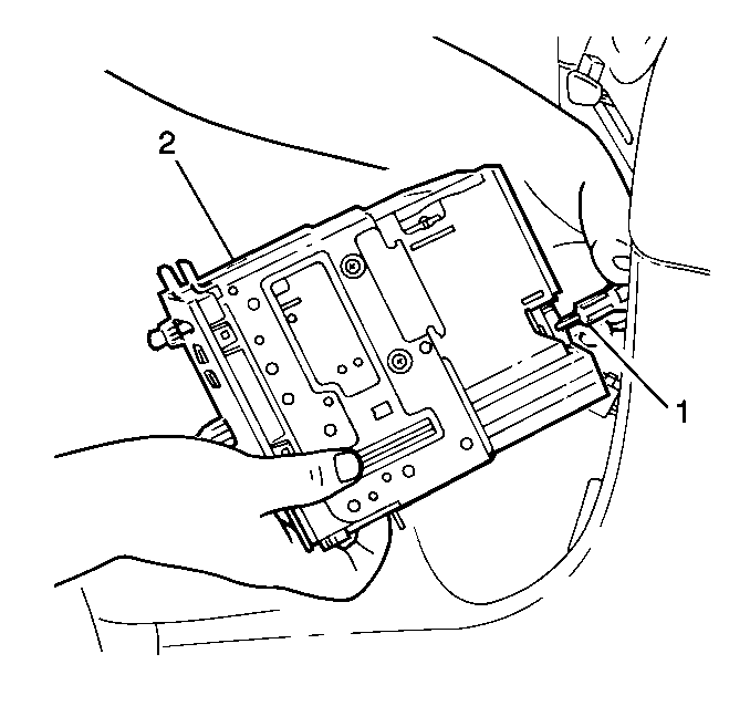
- Connect the following
components to the radio:
| • | The electrical connector |
- Install the radio. Refer to
Radio Replacement
in Entertainment.
- Install the IP accessory center trim plate. Refer to
Instrument Panel Center Trim Panel Replacement
.
- Install the instrument cluster assembly. Refer to
Instrument Cluster Replacement
.
- Install the steering column. Refer to
Steering Column Replacement
in Steering Wheel and Column - Standard
or
Steering Column Replacement
.

- Install the steering column
upper trim cover (2) to the vehicle. Secure the trim cover with the screw
(3).

- Install the steering column
lower trim cover (6) to the vehicle. Secure the trim cover with the 3 screws.
- Install the IP drivers knee bolster reinforcement. Refer to
Knee Bolster Replacement
.
- Install the body hinge pillar trim panels. Refer to
Body Hinge Pillar Trim Panel Replacement
in Interior Trim.
- Enable the SIR system. Refer to
Enabling the SIR System
in SIR.
- Connect the negative battery cable. Refer to
Battery Negative Cable Disconnection and Connection
in Engine Electrical.


