For 1990-2009 cars only
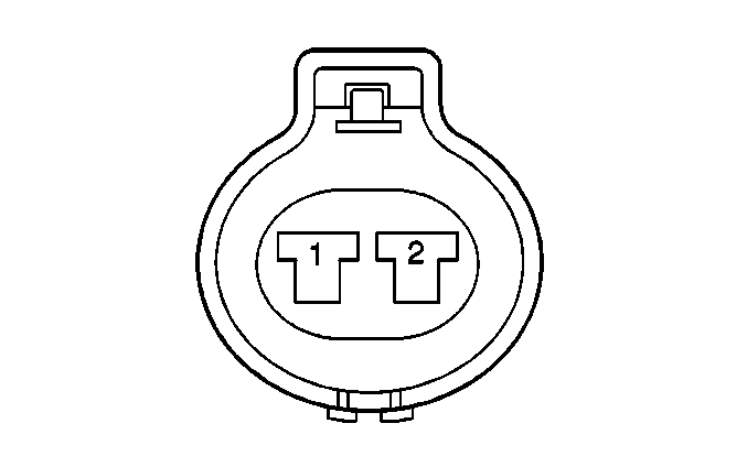
| Table 1: | Main Fan Motor |
| Table 2: | Auxiliary Fan Motor |
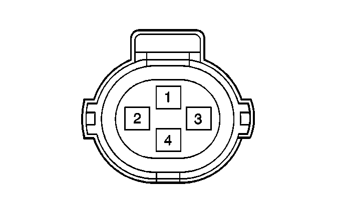
| Table 3: | Refrigerant Pressure Switch |

| ||||||
|---|---|---|---|---|---|---|
Connector Part Information |
| |||||
Pin | Wire Color | Function | ||||
1 | WHT/BLK | Ground | ||||
2 | BLK/RED | Fan No. 1 Relay Output | ||||

| ||||||
|---|---|---|---|---|---|---|
Connector Part Information |
| |||||
Pin | Wire Color | Function | ||||
1 | WHT | No. 2 Fan Relay Output | ||||
2 | BLU/RED | Auxiliary Fan Control | ||||

| ||||||
|---|---|---|---|---|---|---|
Connector Part Information |
| |||||
Pin | Wire Color | Function | ||||
1 | BLU/RED | Heater Relay Output | ||||
2 | LT GRN | Ground | ||||
3 | BLU/BLK | High Speed Fan Control | ||||
4 | YEL/BLK | Pressure Signal to A/C Compressor Control Module | ||||
