Removal Procedure
- Remove the case side cover. Refer to
Control Valve Body Cover Replacement .
- Disconnect the transaxle wiring harness.

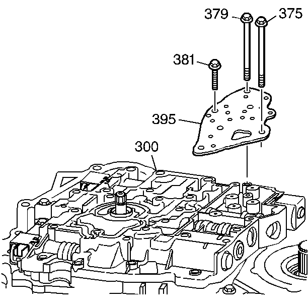
- Remove the control valve body bolts (375, 379, 381) that mount the fluid pressure manual valve position switch to the control valve body (300).
Important: When removing the TFP switch handle the switch carefully, the fluid pressure manual valve position switch is very delicate.
- Carefully remove the fluid pressure manual valve position switch (395).
- Inspect the fluid pressure manual valve position switch (395) for the following conditions:
| • | Damaged electrical connector terminals |
| • | Damaged switch membranes |
| • | Debris on the switch membranes |
Installation Procedure

Important: When installing the TFP switch handle the switch carefully, the fluid pressure manual valve position switch is very delicate.
- Carefully install the fluid pressure manual valve position switch (395).
Notice: Refer to Fastener Notice in the Preface section.
- Install the control valve body bolts (375, 379, 381) that mount the TFP switch to the control valve body (300).
Tighten
| • | Tighten the control valve body bolt (375) to 12 N·m (106 lb in). |
| • | Tighten the control valve body bolt (379) to 16 N·m (12 lb ft). |
| • | Tighten the control valve body bolt (381) to 8 N·m (70 lb in). |
- Connect the transaxle wiring harness.
- Install the case side cover. Refer to
Control Valve Body Cover Replacement .
Important: It is recommended that transmission adaptive pressure (TAP) information be reset.
Resetting the TAP values using a scan tool will erase all learned values in all cells. As a result, The ECM, PCM or TCM will
need to relearn TAP values. Transmission performance may be affected as new TAP values are learned.
- Reset the TAP values. Refer to
Adapt Function.


