| Table 1: | Camshaft Position (CMP) Sensor |
| Table 2: | Crankshaft Position (CKP) Sensor A |
| Table 3: | Crankshaft Position (CKP) Sensor B |
| Table 4: | Engine Coolant Temperature (ECT) Sensor |
| Table 5: | Evaporative Emission (EVAP) Canister Purge Solenoid |
| Table 6: | Evaporative Emission (EVAP) Canister Vent Solenoid |
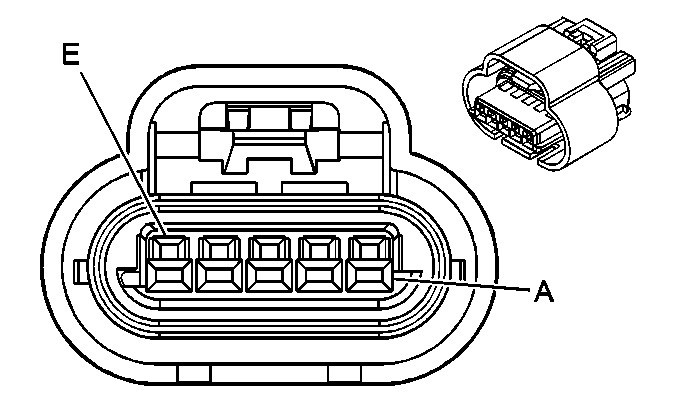
| Table 7: | Exhaust Gas Recirculation (EGR) Valve |
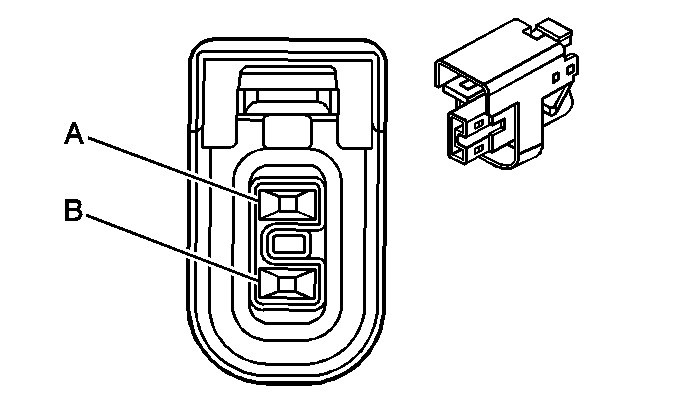
| Table 8: | Fuel Injectors |
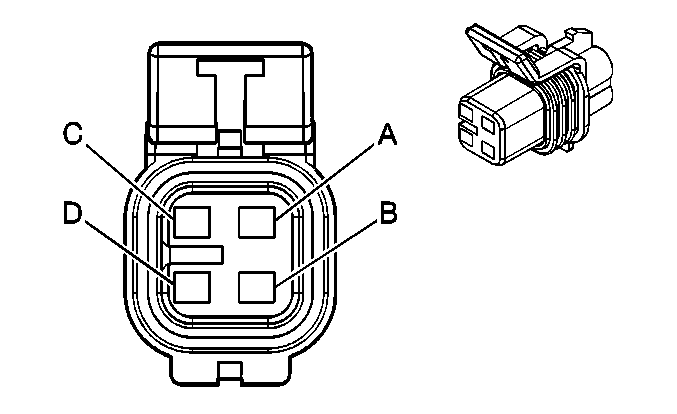
| Table 9: | Fuel Pump and Sender Assembly |
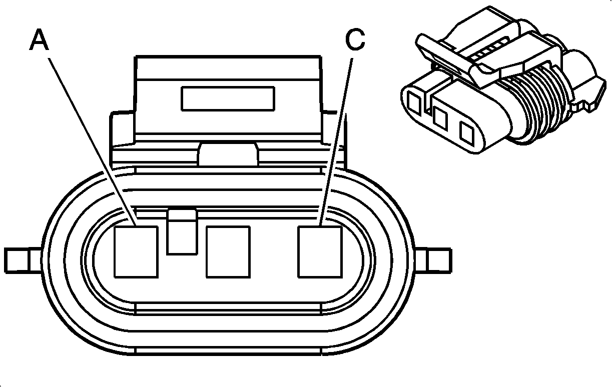
| Table 10: | Fuel Tank Pressure (FTP) Sensor |
| Table 11: | Heated Oxygen Sensor (HO2S) 1 |
| Table 12: | Heated Oxygen Sensor (HO2S) 2 |
| Table 13: | Idle Air Control (IAC) Valve |
| Table 14: | Ignition Control Module (ICM) C1 |
| Table 15: | Ignition Control Module (ICM) C2 |
| Table 16: | Ignition Control Module (ICM) C3 |
| Table 17: | Intake Air Temperature (IAT) Sensor |
| Table 18: | Knock Sensor (KS) |
| Table 19: | Manifold Absolute Pressure (MAP) Sensor |
| Table 20: | Mass Air Flow (MAF) Sensor |
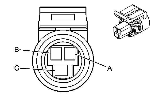
| Table 21: | Throttle Position (TP) Sensor |
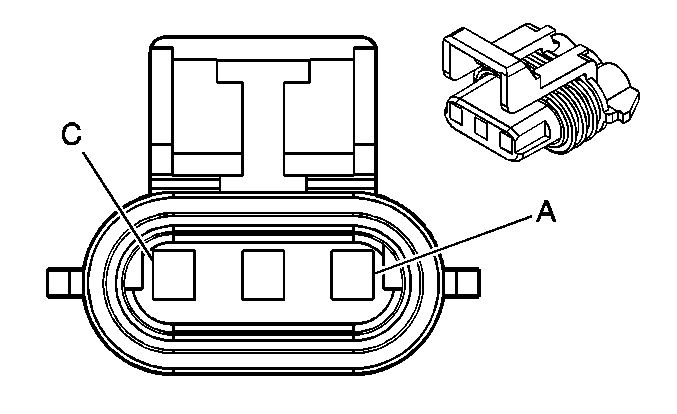
| |||||||
|---|---|---|---|---|---|---|---|
Connector Part Information |
| ||||||
Pin | Wire Color | Circuit No. | Function | ||||
A | RED/WHT | 812 | 12 Volt Reference | ||||
B | BRN/WHT | 633 | CMP Sensor Signal | ||||
C | BLK | 407 | Low Reference | ||||

| |||||||
|---|---|---|---|---|---|---|---|
Connector Part Information |
| ||||||
Pin | Wire Color | Circuit No. | Function | ||||
A | LT GRN | 1867 | 12 Volt Reference | ||||
B | LT BLU/ BLK | 647 | Medium Resolution Engine Speed Signal | ||||
C | YEL/BLK | 1868 | Low Reference | ||||
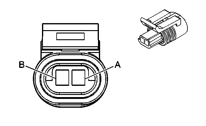
| |||||||
|---|---|---|---|---|---|---|---|
Connector Part Information |
| ||||||
Pin | Wire Color | Circuit No. | Function | ||||
A | YEL | 574 | CKP Sensor Signal | ||||
B | PPL | 573 | Low Reference | ||||

| |||||||
|---|---|---|---|---|---|---|---|
Connector Part Information |
| ||||||
Pin | Wire Color | Circuit No. | Function | ||||
A | ORN/BLK | 469 | Low Reference | ||||
B | YEL | 410 | ECT Sensor Signal | ||||
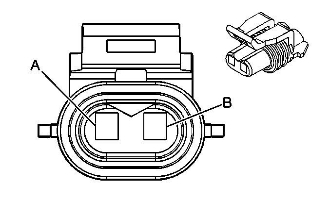
| |||||||
|---|---|---|---|---|---|---|---|
Connector Part Information |
| ||||||
Pin | Wire Color | Circuit No. | Function | ||||
A | BRN | 241 | Ignition 3 Voltage | ||||
B | DK GRN/ WHT | 428 | EVAP Canister Purge Solenoid Control | ||||
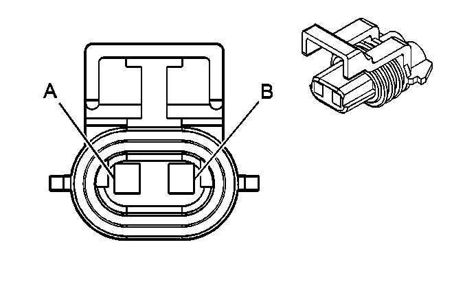
| |||||||
|---|---|---|---|---|---|---|---|
Connector Part Information |
| ||||||
Pin | Wire Color | Circuit No. | Function | ||||
A | BRN | 241 | Ignition 3 Voltage | ||||
B | WHT | 1310 | EVAP Canister Vent Solenoid Control | ||||
| |||||||
|---|---|---|---|---|---|---|---|
Connector Part Information |
| ||||||
Pin | Wire Color | Circuit No. | Function | ||||
A | GRY/BLK | 435 | EGR Solenoid Low Control | ||||
B | BLK | 2753 | Low Reference | ||||
C | BRN/WHT | 1456 | EGR Valve Position Signal | ||||
D | BRN/WHT | 2702 | 5Volt Reference | ||||
E | RED | 1676 | EGR Valve Supply Voltage | ||||
| |||||||
|---|---|---|---|---|---|---|---|
Connector Part Information |
| ||||||
Pin | Wire Color | Circuit No. | Function | ||||
Injector 1 | |||||||
A | PNK | 639 | Ignition 1 Voltage | ||||
B | BLK | 1744 | Fuel Injector 1 Control | ||||
Injector 2 | |||||||
A | PNK | 639 | Ignition 1 Voltage | ||||
B | LT GRN/ BLK | 1745 | Fuel Injector 2 Control | ||||
Injector 3 | |||||||
A | PNK | 639 | Ignition 1 Voltage | ||||
B | PNK/BLK | 1746 | Fuel Injector 3 Control | ||||
Injector 4 | |||||||
A | PNK | 639 | Ignition 1 Voltage | ||||
B | LT BLU/BLK | 844 | Fuel Injector 4 Control | ||||
Injector 5 | |||||||
A | PNK | 639 | Ignition 1 Voltage | ||||
B | BLK/WHT | 845 | Fuel Injector 5 Control | ||||
Injector 6 | |||||||
A | PNK | 639 | Ignition 1 Voltage | ||||
B | YEL/BLK | 846 | Fuel Injector 6 Control | ||||
| |||||||
|---|---|---|---|---|---|---|---|
Connector Part Information |
| ||||||
Pin | Wire Color | Circuit No. | Function | ||||
A | PPL | 1589 | Fuel Level Sensor Signal | ||||
B | GRY | 120 | Fuel Pump Supply Voltage | ||||
C | BLK | 150 | Ground | ||||
D | BLK/WHT | 651 | Low Reference | ||||
| |||||||
|---|---|---|---|---|---|---|---|
Connector Part Information |
| ||||||
Pin | Wire Color | Circuit No. | Function | ||||
A | ORN/BLK | 469 | Low Reference | ||||
B | DK GRN | 890 | Fuel Tank Pressure Sensor Signal | ||||
C | GRY/BLK | 416 | 5Volt Reference | ||||
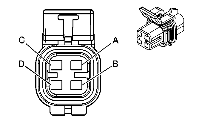
| |||||||
|---|---|---|---|---|---|---|---|
Connector Part Information |
| ||||||
Pin | Wire Color | Circuit No. | Function | ||||
A | TAN | 413 | HO2S Low Reference | ||||
B | PPL | 412 | HO2S 1 High Signal | ||||
C | BLK/WHT | 3113 | HO2S Heater Low Control -- Sensor1 | ||||
D | BRN | 241 | Ignition 3 Voltage | ||||
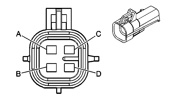
| |||||||
|---|---|---|---|---|---|---|---|
Connector Part Information |
| ||||||
Pin | Wire Color | Circuit No. | Function | ||||
A | TAN/WHT | 1669 | HO2S Low Signal-- Bank 1 Sensor 2 | ||||
B | PPL/WHT | 1668 | HO2S High Signal-- Bank 1 Sensor 2 | ||||
C | BLK | 150 | Ground | ||||
D | BRN | 241 | Ignition 3 Voltage | ||||
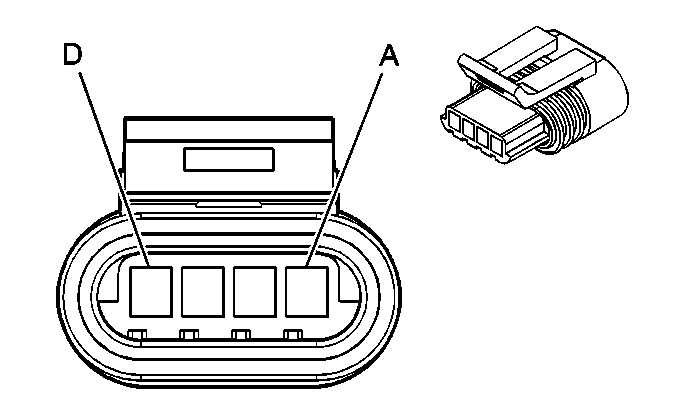
| |||||||
|---|---|---|---|---|---|---|---|
Connector Part Information |
| ||||||
Pin | Wire Color | Circuit No. | Function | ||||
A | LT GRN/ BLK | 444 | IAC Coil B Low Control | ||||
B | LT GRN/ WHT | 1749 | IAC Coil B High Control | ||||
C | LT BLU/ BLK | 1748 | IAC Coil A Low Control | ||||
D | LT BLU/ WHT | 1747 | IAC Coil A High Control | ||||
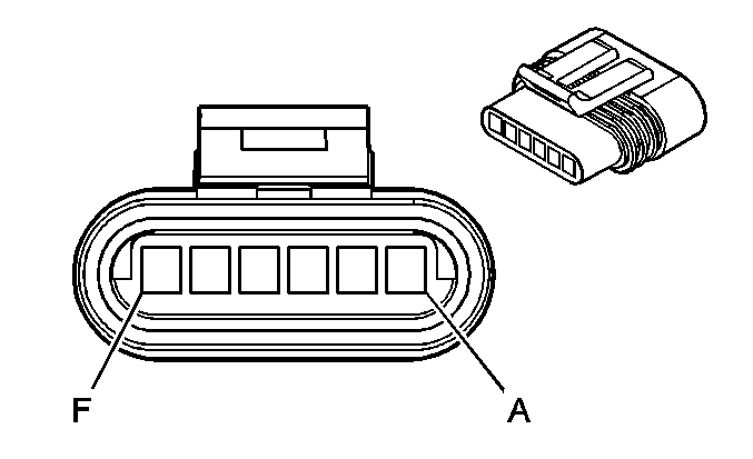
| |||||||
|---|---|---|---|---|---|---|---|
Connector Part Information |
| ||||||
Pin | Wire Color | Circuit No. | Function | ||||
A | TAN/BLK | 424 | IC Timing Signal | ||||
B | WHT | 423 | IC Timing Control | ||||
C-D | -- | -- | Not Used | ||||
E | PPL/WHT | 430 | Low Resolution Engine Speed Signal | ||||
F | RED/BLK | 453 | Low Reference | ||||
| |||||||
|---|---|---|---|---|---|---|---|
Connector Part Information |
| ||||||
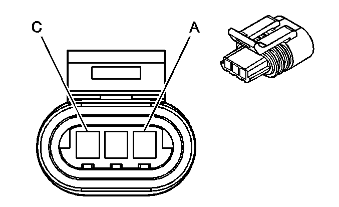
Pin | Wire Color | Circuit No. | Function | ||||
A | YEL | 573 | CKP Sensor Signal | ||||
B | -- | -- | Not Used | ||||
C | PPL | 574 | Low Reference | ||||

| |||||||
|---|---|---|---|---|---|---|---|
Connector Part Information |
| ||||||
Pin | Wire Color | Circuit No. | Function | ||||
A | BLK | 450 | Ground | ||||
B | PNK | 239 | Ignition 1 Voltage | ||||
| |||||||
|---|---|---|---|---|---|---|---|
Connector Part Information |
| ||||||
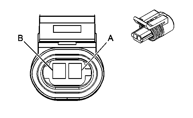
Pin | Wire Color | Circuit No. | Function | ||||
A | BLK | 2760 | Low Reference | ||||
B | TAN | 472 | IAT Sensor Signal | ||||
| |||||||
|---|---|---|---|---|---|---|---|
Connector Part Information |
| ||||||
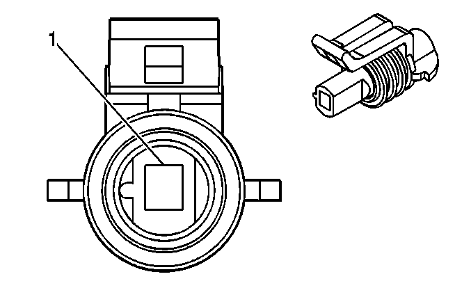
Pin | Wire Color | Circuit No. | Function | ||||
1 | DK BLU | 496 | KS Signal | ||||
| |||||||
|---|---|---|---|---|---|---|---|
Connector Part Information |
| ||||||
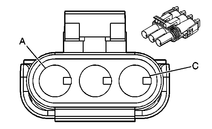
Pin | Wire Color | Circuit No. | Function | ||||
A | ORN/BLK | 469 | Low Reference | ||||
B | LT GRN | 432 | MAP Sensor Signal | ||||
C | GRY | 2704 | 5 Volt Reference | ||||

| |||||||
|---|---|---|---|---|---|---|---|
Connector Part Information |
| ||||||
Pin | Wire Color | Circuit No. | Function | ||||
A | YEL | 492 | MAF Sensor Signal | ||||
B | BLK/WHT | 451 | Ground | ||||
C | PNK | 639 | Ignition 1 Voltage | ||||
| |||||||
|---|---|---|---|---|---|---|---|
Connector Part Information |
| ||||||
Pin | Wire Color | Circuit No. | Function | ||||
A | GRY/BLK | 2701 | 5 Volt Reference | ||||
B | BLK | 2752 | Low Reference | ||||
C | DK BLU | 417 | TP Sensor Signal | ||||
