Removal Procedure
- Remove the case side cover. Refer to
Control Valve Body Cover Replacement .
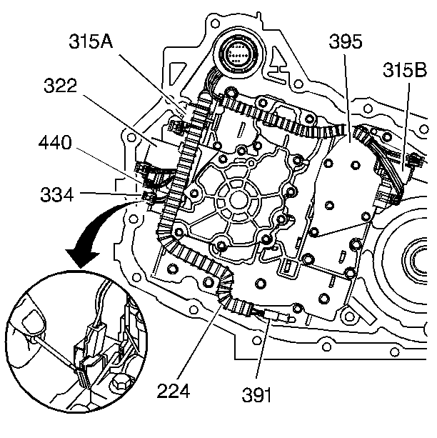
- Disconnect and reposition the electrical connectors from the following:
| • | If equipped internal mode switch |
| • | 2-3 Shift solenoid valve assembly (315B) |
| • | Automatic transaxle fluid pressure manual valve position switch assembly (395) |
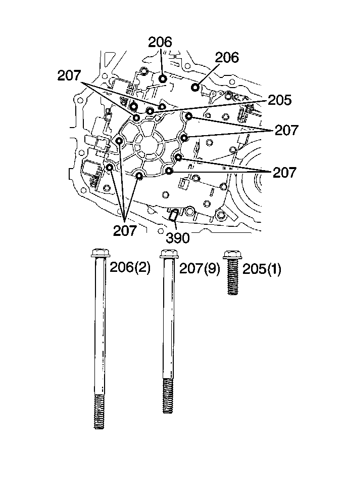
Important: Do NOT remove the bolt (205) that holds the oil pump together.
- Remove the oil pump bolts (206,207).
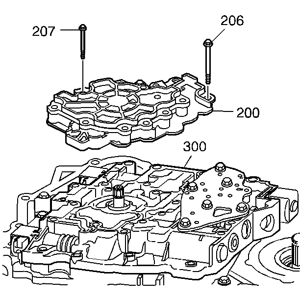
- Remove the oil pump (200) from the valve body (300).
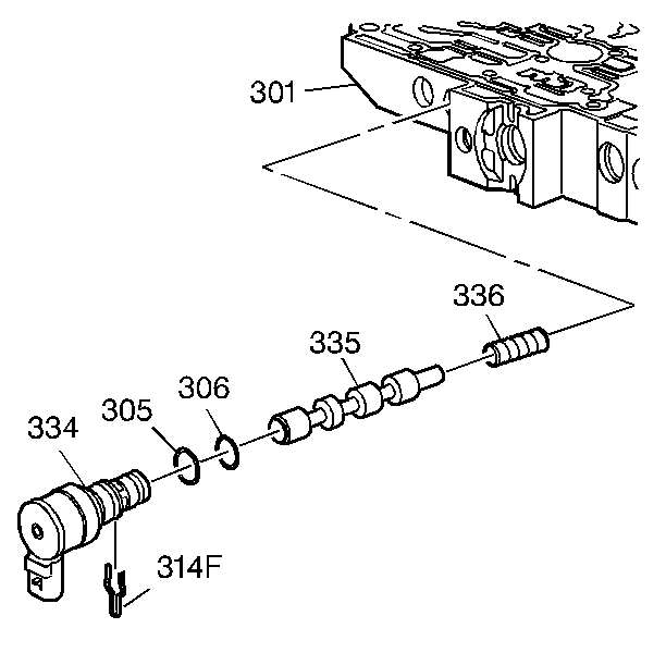
- Disconnect the torque converter clutch pulse width modulation (TCC PWM) solenoid electrical connector.
- Remove the TCC PWM solenoid retaining clip (314F).
- Remove the TCC PWM solenoid (334).
Installation Procedure
- Install the TCC PWM solenoid (334).
- Install the TCC PWM solenoid retaining clip (314F).
- Connect the TCC PWM solenoid electrical connector.
- Install the oil pump (200) to the valve body (300).
Notice: Refer to Fastener Notice in the Preface section.
- Install the oil pump body and cover bolts (206,207).
Tighten
| • | Tighten the bolts (207) to 12 N·m (106 lb in). |
| • | Tighten the bolts (206) to 16 N·m (12 lb ft). |
- Reposition and connect the electrical connectors to the following:
| • | Automatic transaxle fluid pressure manual valve position switch assembly (395) |
| • | 2-3 Shift solenoid valve assembly (315B) |
| • | If equipped internal mode switch |
- Install the case side cover. Refer to
Control Valve Body Cover Replacement .
Important: It is recommended that transmission adaptive pressure (TAP) information be reset.
Resetting the TAP values using a scan tool will erase all learned values in all cells. As a result, The ECM, PCM or TCM will
need to relearn TAP values. Transmission performance may be affected as new TAP values are learned.
- Reset the TAP values. Refer to
Adapt Function.
