Step
| Action
| Values
| Yes
| No
|
Schematic Reference:
Engine Controls Schematics
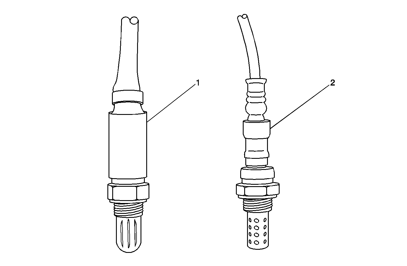
Important: This diagnostic applies only to vehicles built with Denso heated oxygen
sensors. To identify the heated oxygen sensor, refer to
|
1
| Did you perform the Diagnostic System Check-Engine
Controls?
| --
| Go to
Step 2
| Go to
Diagnostic System Check - Engine Controls
|
2
|
Important: Allow the engine to cool for one-half hour before proceeding with
this diagnostic. This allows the HO2S signal voltage to return to bias voltage,
approximately 447 mV.
- Install a scan tool.
- Turn ON the ignition, with the engine OFF.
- Immediately observe the affected HO2S voltage for 2 minutes.
Does the HO2S voltage go from bias voltage to more than or less than
the specified range?
| 350-550 mV
| Go to
Step 3
| Go to
Step 5
|
3
|
- Start the engine.
- Allow the engine to reach operating temperature.
- Raise and hold the engine speed at 1,200 RPM for 2 minutes.
- Observe the HO2S voltage with a scan tool.
Is the HO2S voltage varying outside the specified range?
| 410-490 mV
| Go to
Step 4
| Go to
Step 5
|
4
|
- Observe the Freeze Frame/Failure Records data for this DTC.
- Turn OFF the ignition for 30 seconds.
- Start the engine.
- Operate the vehicle within the Conditions for Running the DTC
as specified in the supporting text or as close to the Freeze Frame/Failure
Records data that you observed.
Does the DTC fail this ignition?
| --
| Go to
Step 5
| Go to
Intermittent Conditions
|
5
| Are Both DTCs P0140 and P0160 set?
| --
| Go to
Step 6
| Go to
Step 7
|
6
|
- Turn OFF the ignition.
- Disconnect the bank 1 sensor 2 HO2S connector.
- Probe the HO2S low reference circuit with a test lamp that is
connected to battery positive.
Does the test lamp illuminate?
| --
| Go to
Step 11
| Go to
Step 10
|
7
|
- Turn OFF the ignition.
- Disconnect the affected HO2S connector.
- Jumper the HO2S high signal circuit to the low reference circuit.
- Turn ON the ignition, with the engine OFF.
- Observe the HO2S voltage with a scan tool.
Is the HO2S voltage less than the specified value?
| 200 mV
| Go to
Step 11
| Go to
Step 8
|
8
|
- Turn OFF the ignition.
- Disconnect the PCM connector containing the HO2S high signal circuit.
Refer to
Powertrain Control Module Replacement
.
- Test the HO2S high signal circuit for an open. Refer to
Circuit Testing
and
Wiring Repairs
in Wiring Systems.
Did you find and correct the condition?
| --
| Go to
Step 23
| Go to
Step 9
|
9
| Test for an open between terminal A of the affected sensor harness connector
and one of the following PCM terminals:
| • | If DTC P0140 is set, use C1-28 |
| • | If DTC P0160 is set, use C1-25 |
Refer to
Circuit Testing
and
Wiring Repairs
in Wiring Systems.
Did you find and correct the condition?
| --
| Go to
Step 23
| Go to
Step 18
|
10
|
- Disconnect the PCM connector containing the HO2S low reference
circuit. Refer to
Powertrain Control Module Replacement
.
- Test the low reference circuit for an open between HO2S bank 1
sensor 2 terminal A and PCM terminal C1-63.
Refer to
Circuit Testing
and
Wiring Repairs
in Wiring Systems.
Did you find and correct the condition?
| --
| Go to
Step 23
| Go to
Step 18
|
11
| Remove the jumper from the previous step, if applicable.
Is the O2B fuse open?
| --
| Go to
Step 14
| Go to
Step 12
|
12
|
- Turn ON the ignition, with the engine OFF.
- Probe the affected HO2S ignition 1 voltage circuit with a test
lamp that is connected to a good ground.
Does the test lamp illuminate?
| --
| Go to
Step 13
| Go to
Step 19
|
13
|
- Connect a test lamp between the affected HO2S ignition 1 voltage
circuit and the HO2S heater ground circuit.
- Turn ON the ignition, with the engine OFF.
Does the test lamp illuminate?
| --
| Go to
Step 17
| Go to
Step 20
|
14
|
- Disconnect the opposite bank HO2S pigtail connector.
- Test the HO2S ignition 1 voltage circuit for a short to ground.
Refer to
Circuit Testing
and
Wiring Repairs
in Wiring Systems.
- Replace the O2B fuse.
Did you find and correct a short to ground in the ignition 1 voltage
circuit?
| --
| Go to
Step 23
| Go to
Step 15
|
15
|
Important: Perform the following test on HO2S bank 1 sensor 2 and HO2S bank 2 sensor
2. A condition in either sensor will cause this DTC to set.
Test the HO2S ignition 1 voltage circuit, sensor side, for a short to
the HO2S body. Refer to
Circuit Testing
in
Wiring Systems.
Did you find the condition?
| --
| Go to
Step 21
| Go to
Step 16
|
16
|
Important: Perform the following test on HO2S bank 1 sensor 2 and HO2S bank 2 sensor
2. A condition in either sensor will cause this DTC to set.
Measure the resistance between the HO2S ignition 1 voltage circuit,
sensor side, and the HO2S heater ground circuit, sensor side. Refer to
Circuit Testing
in Wiring Systems.
Does the resistance of either sensor measure above or below the specified
range?
| 2-50 ohms
| Go to
Step 21
| Go to
Intermittent Conditions
|
17
| Inspect for
poor connections at the harness connector of the affected HO2S. Refer to
Testing for Intermittent Conditions and Poor Connections
and
Connector Repairs
in Wiring Systems.
Did you find and correct the condition?
| --
| Go to
Step 23
| Go to
Step 21
|
18
| Inspect for poor connections at the harness connector of the PCM. Refer
to
Testing for Intermittent Conditions and Poor Connections
and
Connector Repairs
in
Wiring Systems.
Did you find and correct the condition?
| --
| Go to
Step 23
| Go to
Step 22
|
19
| Repair the open in the ignition 1 voltage circuit. Refer to
Circuit Testing
and
Wiring Repairs
in Wiring Systems.
Did you complete the repair?
| --
| Go to
Step 23
| --
|
20
| Repair the open in the HO2S heater ground circuit. Refer to
Wiring Repairs
in Wiring Systems.
Did you complete the repair?
| | Go to
Step 23
| --
|
21
| Replace the affected HO2S refer to
Heated Oxygen Sensor Replacement - Bank 1 Sensor 2
or
Heated Oxygen Sensor Replacement - Bank 2 Sensor 2
.
Did you complete the replacement?
| --
| Go to
Step 23
| --
|
22
| Replace the PCM. Refer to
Powertrain Control Module Replacement
.
Did you complete the replacement?
| --
| Go to
Step 23
| --
|
23
|
- Use the scan tool in order to clear the DTCs.
- Turn OFF the ignition for 30 seconds.
- Start the engine.
- Operate the vehicle within the Conditions for Running the DTC
as specified in the supporting text.
Does the DTC run and pass?
| --
| Go to
Step 24
| Go to
Step 2
|
24
| With a scan tool, observe the stored information, Capture info.
Does the scan tool display any DTCs that you have not diagnosed?
| --
| Go to
Diagnostic Trouble Code (DTC) List
| System OK
|
