Clutch Assembly Replacement 6.6L w/RPO MZE
Tools Required
| • | J 26455-A Clutch Alignment Arbor |
| • | J 35990 Clutch Alignment Arbor |
Removal Procedure
- Remove the transmission. Refer to Transmission Replacement in Manual Transmission - Medium Duty.
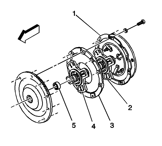
- Remove the clutch pressure plate bolts and washers.
- Remove the clutch pressure plate (1).
- Remove the clutch driven plate (2).
- Remove the clutch intermediate plate (3).
- Remove the clutch front drive plate (4).
- Remove the clutch pilot bearing (5), if necessary.
Inspection
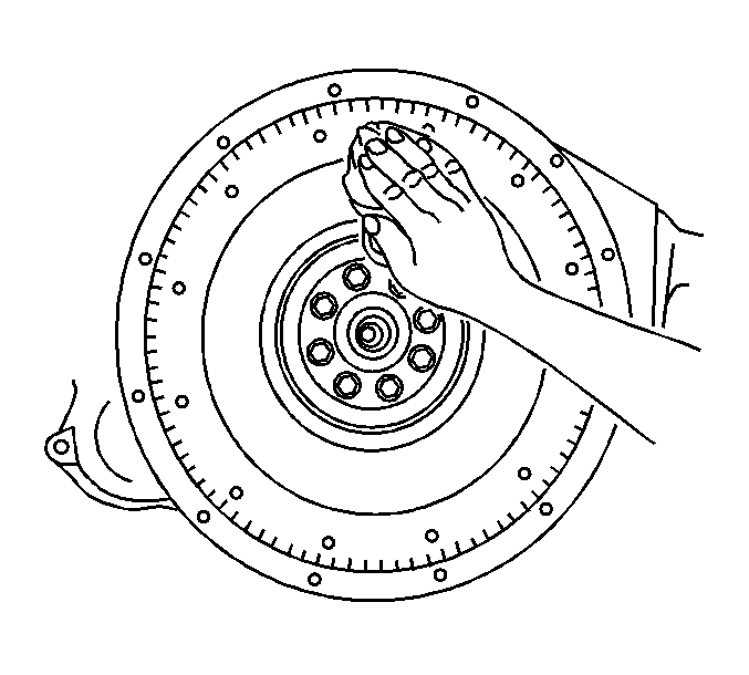
- Remove any grease, dirt or oil from the flywheel surface.
- Inspect the following items for wear:
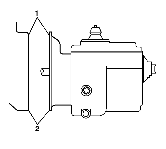
- Inspect the mating surfaces of the engine and bellhousing (1, 2), replace as necessary.
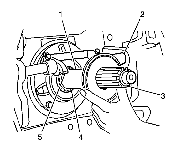
| • | Smooth are of the input shaft (1) |
| • | Cross-shafts and bushings (2) |
| • | Splines on the input shaft (3) |
| • | Release yoke fingers (5) |
Installation Procedure
- Install the clutch pilot bearing, if necessary.
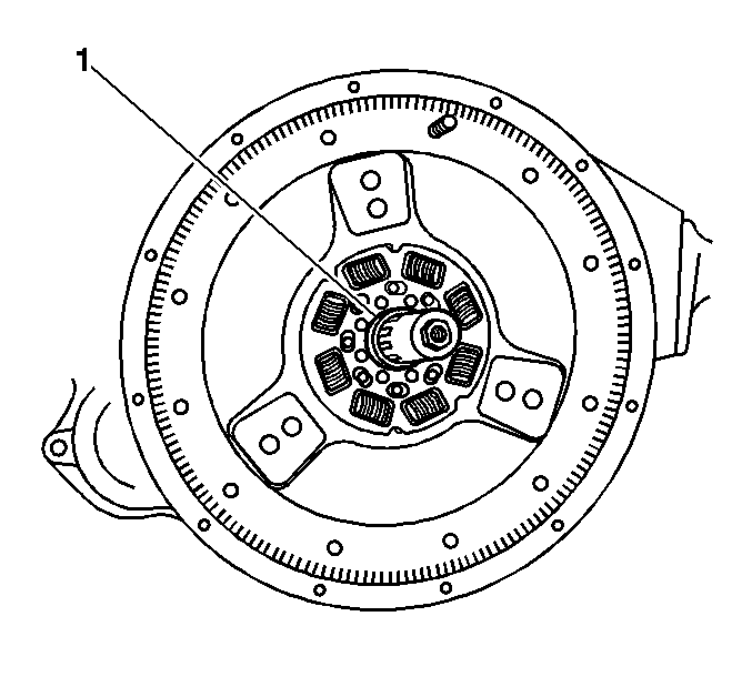
- Install the clutch driven rear plate by inserting the J 26455-A or J 35990 (1) through the plate splines and into the pilot shaft.
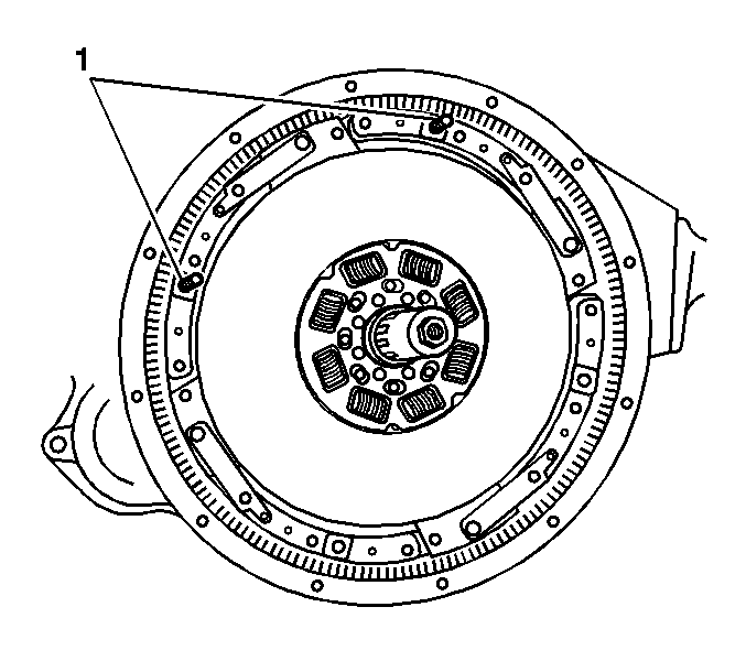
- Install two 3/8 x 16 x 3 inch long guide studs (1).
- Install the clutch intermediate plate over the studs and forward until the plate touches the flywheel.
- Remove the J 26455-A or J 35990 .
- Install the J 26455-A orJ 35990 through the splines of the clutch driven rear plate, and insert the J 26455-A or J 35990 with the rear plate into the pilot bearing.
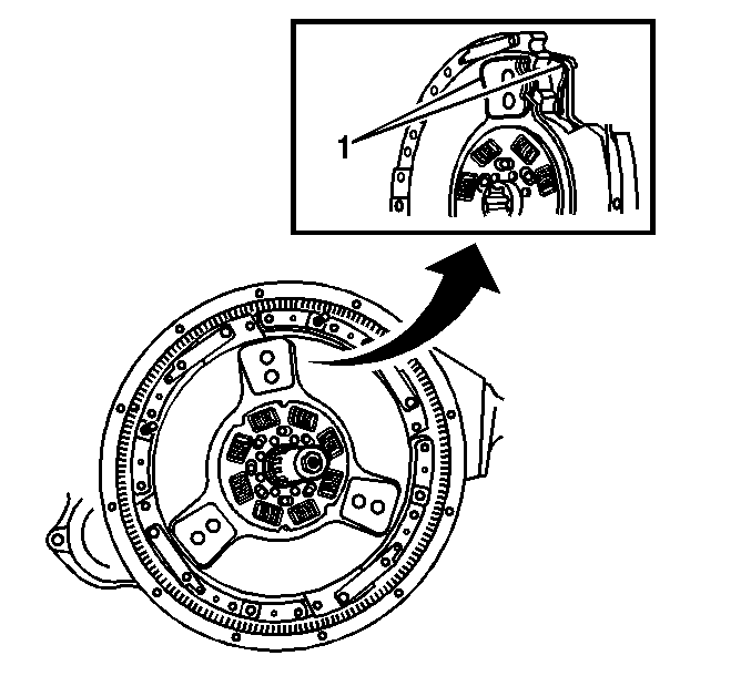
- Ensure that the ceramic buttons (1) align with each other as closely as possible, in order to aid the function of the positive roll pins.
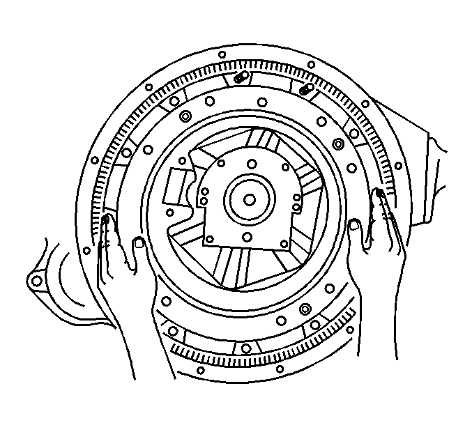
- Slide the pressure plate over both the guide studs and the J 26455-A orJ 35990 , until it rest against the intermediate plate.
- Install 6 clutch pressure plate bolts, with washers, until finger tight.
- Remove the2 guide studs, and install the final 2 clutch pressure plate bolts, with washers, finger tight.
- Tighten the clutch pressure plate bolts, in the sequence shown.
- Tighten the clutch pressure plate bolts a first pass to 20 N·m (15 lb ft).
- Tighten the clutch pressure plate bolts a final pass to 40 N·m (30 lb ft).
- Remove the J 26455-A or J 35990 .
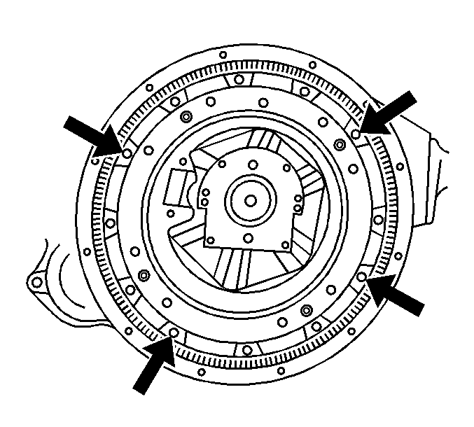
- Using a hammer and a flat nose punch, lightly tap the 4 roll pins through the access holes, as shown, of the clutch cover.
- Ensure that the roll pins are against the flywheel, this will allow an equal gap on all sides of the intermediate plate during clutch disengagement.
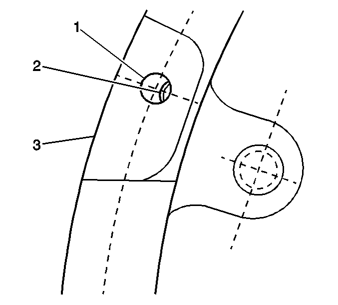
- Only a small portion of the roll pin (2) will be visible through the access hole (1) of the pressure plate (3).
- When installed correctly, and the roll pins (2) are correctly positioned, there should be a gap (4) between the roll pin and the pressure plate (6). This will allow the intermediate plate (5) to move back and free the front disc.
- Install the transmission. Refer to Transmission Replacement in Manual Transmission - Medium Duty.
- Reset the clutch. Refer to Clutch Assembly Adjustment .
Important: Ensure that the side marked "Flywheel Side" faces the flywheel.
Important: Ensure that the side marked "Pressure Plate Side" is facing the pressure plate.
Important: Ensure that the side marked "Pressure Plate Side" is facing the pressure plate.

Notice: Use the correct fastener in the correct location. Replacement fasteners must be the correct part number for that application. Fasteners requiring replacement or fasteners requiring the use of thread locking compound or sealant are identified in the service procedure. Do not use paints, lubricants, or corrosion inhibitors on fasteners or fastener joint surfaces unless specified. These coatings affect fastener torque and joint clamping force and may damage the fastener. Use the correct tightening sequence and specifications when installing fasteners in order to avoid damage to parts and systems.
Tighten
Important: The roll pins may be damaged of struck with excessive force.

Specification
Gap between roll pin and clutch cover 0.5 - 0.8 mm (0.020 - 0.030 in).
Clutch Assembly Replacement 7.2L w/RPO MWM
Tools Required
| • | J 26455-A Clutch Alignment Arbor |
| • | J 35990 Clutch Alignment Arbor |
Removal Procedure
- Remove the transmission. Refer to Transmission Replacement in Manual Transmission - Medium Duty.
- Remove the clutch pressure plate bolts and washers.
- Remove the clutch pressure plate (1).
- Remove the clutch driven plate (2).
- Remove the clutch pilot bearing (3), if necessary.

Inspection
- Remove any grease, dirt or oil from the flywheel surface.
- Inspect the following items for wear:
- Inspect the mating surfaces of the engine and bellhousing (1, 2), replace as necessary.

| • | Smooth are of the input shaft |
| • | Splines on the input shaft |

Installation Procedure
- Install the clutch pilot bearing, if necessary.
- Install the clutch drive plate (2) by inserting the J 26455-A or J 35990 through the plate splines and into the pilot shaft.
- Install two clutch locating pins 180 degrees apart on the flywheel.
- Install the clutch pressure plate (1) over the alignment pins.
- Install 6 clutch pressure plate bolts, with washers, until finger tight.
- Remove the 2 locating pins, and install the final 2 clutch pressure plate bolts, with washers, finger tight.
- Tighten the clutch pressure plate bolts, in the sequence shown.
- Remove the J 26455-A or J 35990 .
- Install the transmission. Refer to Transmission Replacement in Manual Transmission - Medium Duty.
- Reset the clutch. Refer to Clutch Assembly Adjustment .

Important: Ensure that the side marked "Flywheel Side" faces the flywheel.

Notice: Use the correct fastener in the correct location. Replacement fasteners must be the correct part number for that application. Fasteners requiring replacement or fasteners requiring the use of thread locking compound or sealant are identified in the service procedure. Do not use paints, lubricants, or corrosion inhibitors on fasteners or fastener joint surfaces unless specified. These coatings affect fastener torque and joint clamping force and may damage the fastener. Use the correct tightening sequence and specifications when installing fasteners in order to avoid damage to parts and systems.
Tighten
Tighten the clutch pressure plate bolts to 54 N·m (40 lb ft).
Clutch Assembly Replacement 6.6L/7.2L w/RPO MTD
Tools Required
| • | J 26455-A Clutch Alignment Arbor |
| • | J 35990 Clutch Alignment Arbor |
Removal Procedure
- Remove the transmission. Refer to Transmission Replacement in Manual Transmission - Medium Duty.
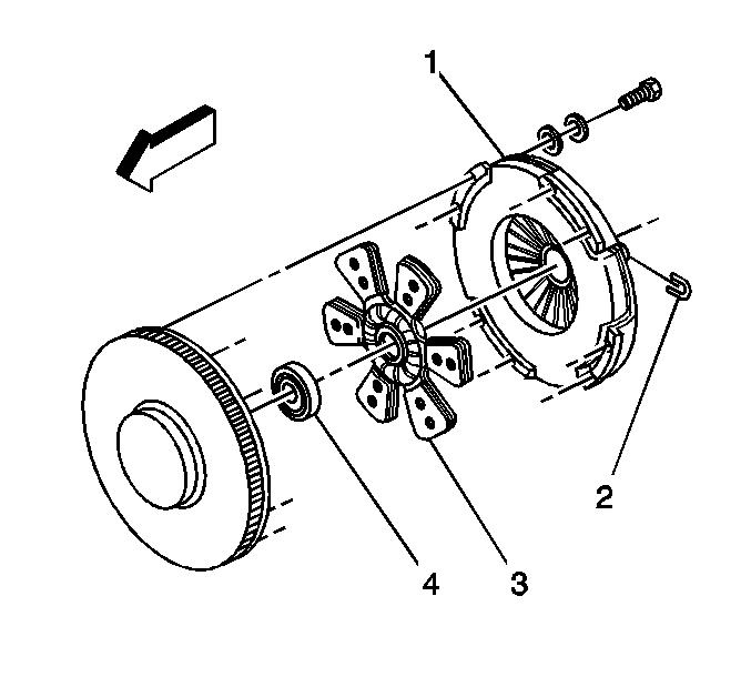
- Remove the clutch pressure plate bolts and washers.
- Remove the clutch pressure plate (1).
- Remove the clutch driven plate (3).
- Remove the clutch pilot bearing (4), if necessary.
Inspection
- Remove any grease, dirt or oil from the flywheel surface.
- Inspect the following items for wear:
- Inspect the mating surfaces of the engine and bellhousing (1, 2), replace as necessary.


| • | Smooth are of the input shaft (1) |
| • | Cross-shafts and bushings (2) |
| • | Splines on the input shaft (3) |
| • | Release yoke fingers (5) |

Installation Procedure
- Install the clutch pilot bearing, if necessary.
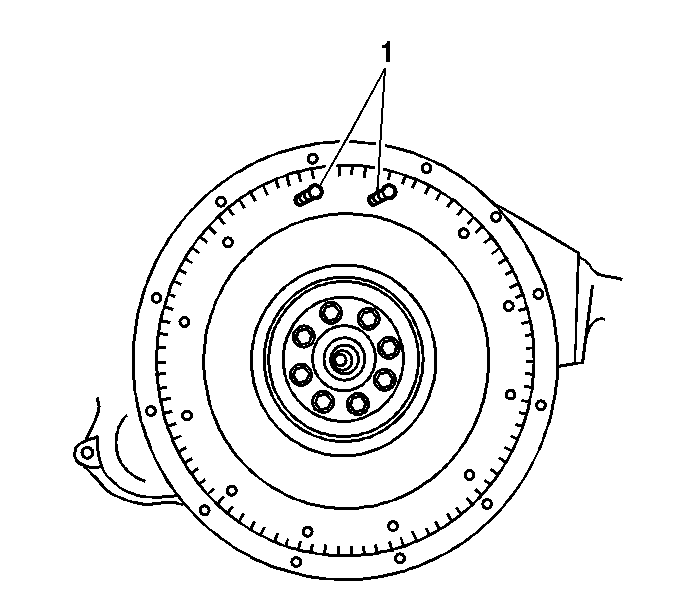
- Install two 3/8 x 16 x 3 inch long (76 mm) guide studs (1) at the 11 o'clock and 1 o'clock positions on the flywheel.
- Apply lubrication to the hub splines.
- Install the Title not found or J 35990 (1).
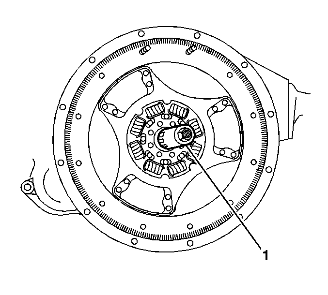
- Install the driven plate by sliding the plate over the J 26455-A or J 35990 (1) splines and into the pilot bearing.
- Install the clutch pressure plate over the J 26455-A or J 35990 (1) and the guide studs.
- Install 6 clutch pressure plate bolts, with washers, until finger tight.
- Remove the 2 guide studs, and install the final 2 clutch pressure plate bolts, with washers, finger tight.
- Tighten the clutch pressure plate bolts, in the sequence shown.
- Tighten the clutch pressure plate bolts a first pass to 20 N·m (15 lb ft).
- Tighten the clutch pressure plate bolts a final pass to 40 N·m (30 lb ft).
- Using a hex-head socket, remove the four yellow colored shipping bolts in a criss-cross pattern.
- Remove the J 26455-A or J 35990 (1).
- Install the transmission. Refer to Transmission Replacement in Manual Transmission - Medium Duty.
- Reset the clutch. Refer to Clutch Assembly Adjustment .
Important: Ensure that the side marked "Pressure Plate Side" faces the pressure plate.

Notice: Use the correct fastener in the correct location. Replacement fasteners must be the correct part number for that application. Fasteners requiring replacement or fasteners requiring the use of thread locking compound or sealant are identified in the service procedure. Do not use paints, lubricants, or corrosion inhibitors on fasteners or fastener joint surfaces unless specified. These coatings affect fastener torque and joint clamping force and may damage the fastener. Use the correct tightening sequence and specifications when installing fasteners in order to avoid damage to parts and systems.
Tighten

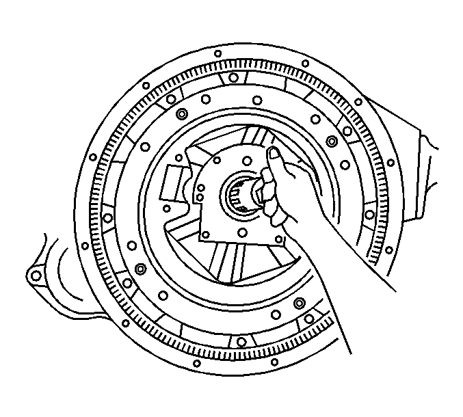
Important: Save these bolts for future use. Should the clutch need to be removed and then re-installed, the shipping bolts must be re-installed snugly prior to the clutch removal. If the clutch has been removed, the clutch must be reset.
Clutch Assembly Replacement 8.1L w/RPO MPJ
Tools Required
| • | J 26455-A Clutch Alignment Arbor |
| • | J 35990 Clutch Alignment Arbor |
Removal Procedure
- Remove the transmission. Refer to Transmission Replacement in Manual Transmission - Medium Duty.
- Remove the clutch pressure plate bolts.
- Remove the clutch pressure plate (2).
- Remove the clutch driven plate (1).
- Remove the clutch pilot bearing, if necessary.
- Remove any grease, dirt or oil from the flywheel surface.


Installation Procedure
- Install the clutch pilot bearing, if necessary.
- Install the clutch driven plate (1) by inserting the J 26455-A or J 35990 through the plate splines and into the pilot bearing.
- Install two clutch locating pins 180 degrees apart on the flywheel.
- Install the clutch pressure plate (2) over the alignment pins.
- Install the clutch pressure plate bolts finger tight.
- Remove the J 26455-A or J 35990 .
- Install the transmission. Refer to Transmission Replacement in Manual Transmission - Medium Duty.
- Reset the clutch. Refer to Clutch Assembly Adjustment .

Important: Ensure that the side marked "Flywheel Side" faces the flywheel.

Notice: Use the correct fastener in the correct location. Replacement fasteners must be the correct part number for that application. Fasteners requiring replacement or fasteners requiring the use of thread locking compound or sealant are identified in the service procedure. Do not use paints, lubricants, or corrosion inhibitors on fasteners or fastener joint surfaces unless specified. These coatings affect fastener torque and joint clamping force and may damage the fastener. Use the correct tightening sequence and specifications when installing fasteners in order to avoid damage to parts and systems.
Tighten the clutch pressure plate bolts, in the sequence shown.
Tighten
Tighten the clutch pressure plate bolts to 70 N·m (52 lb ft).
