GM Service Manual Online
For 1990-2009 cars only
Makes
🢒
Chevrolet
🢒
2002
🢒
Chevrolet C-Series Medium Duty Truck B7
🢒
Engine
🢒
Engine Electrical
🢒 Starting and Charging Schematics
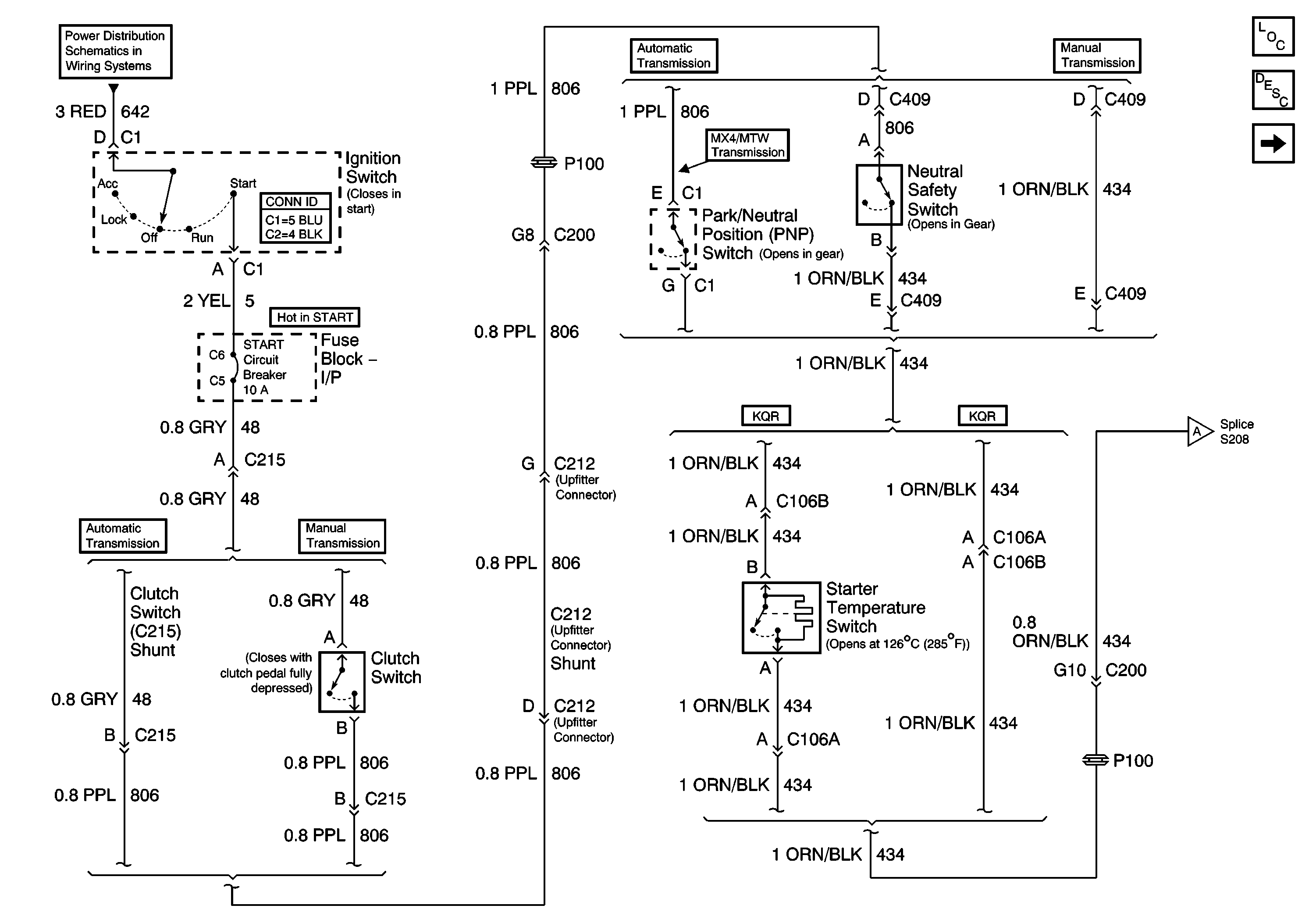
Figure
1:
Starting Circuit (1 of 2) LG5
Master Electrical Component List
Starting System Description and Operation
Starting and Charging Schematics - LG5 Starting Circuit (2of2)
Power Distribution Schematics - ACC, B/U, Chassis, ING 1, ING 3 and Start Circuit Breakers
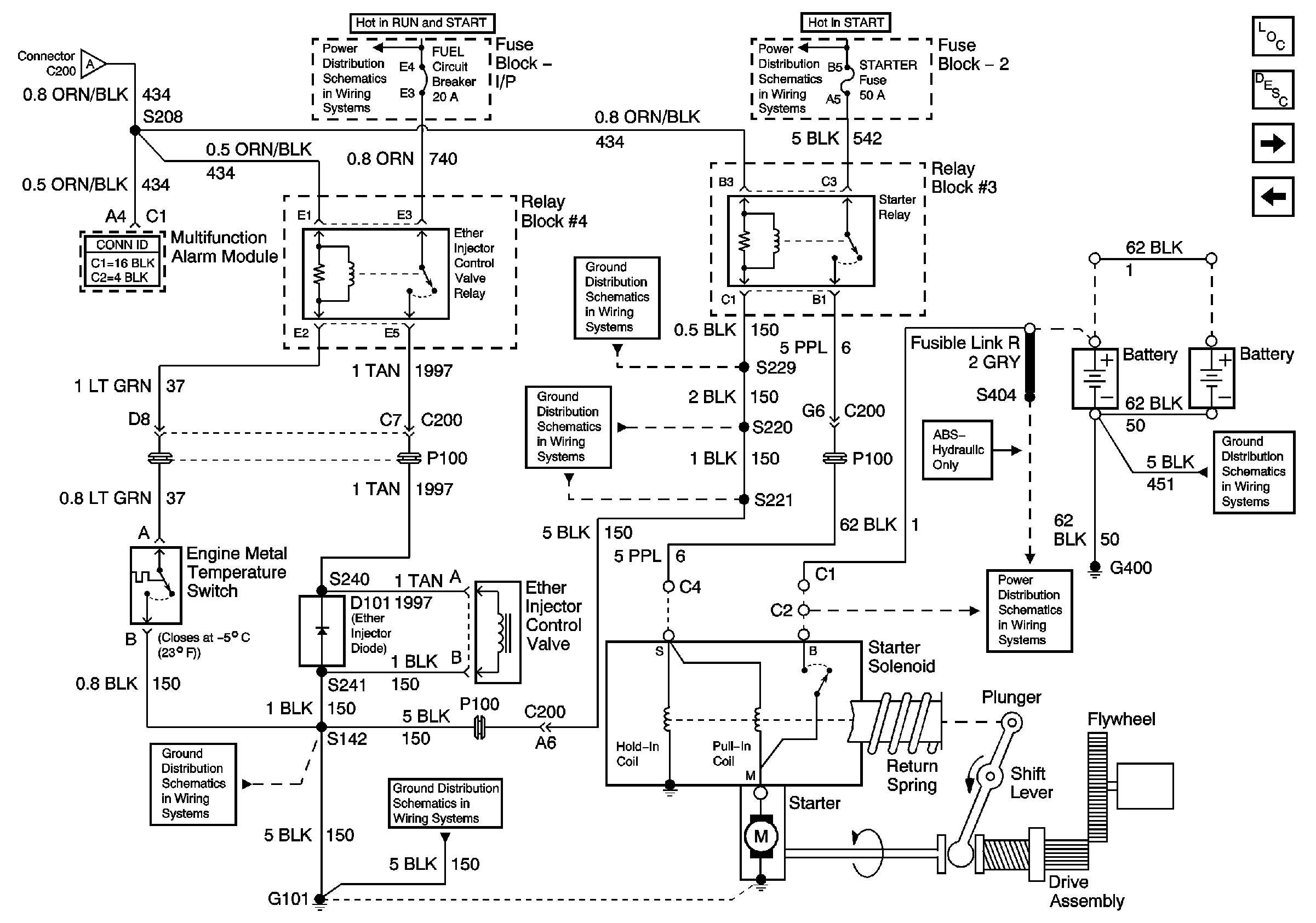
Figure
2:
Starting Circuit (2 of 2) LG5
Starting and Charging Schematics - LG5 Starting Circuit (1of2)
Power Distribution Schematics - Aux 1, Aux 2, ECM, ENG, ETM and Fuel Circuit Breakers, Aux, Body Power 1 and Engine Fuses
Power Distribution Schematics - ABS, Body Power 2, ING SW 2, Lighting, PCM/Injectors and Starter Fuses, Even and ODD INJ, HAZ, PNL, and TL/MKR Circuit Breakers
Master Electrical Component List
Starting System Description and Operation
Starting and Charging Schematics - LG5 Charging Circuit
Starting and Charging Schematics - LG5 Starting Circuit (1of2)
Ground Distribution Schematics - S220, S229 LG5
Ground Distribution Schematics - G108, G207, G208 and S221 LG5
Ground Distribution Schematics - G100, G101, G103, G107, G117, G119, G120, G121, G124, G400, G401, G405, G412, G413, G414, S170
Battery and BRK, HORNS, and STOP LP Circuit Breakers, HD LP SW, HORN/STOP and IGN SW 1 Fuses
Ground Distribution Schematics - S142 and S241 LG5
Ground Distribution Schematics - G101, S138, S405 and S409 L18
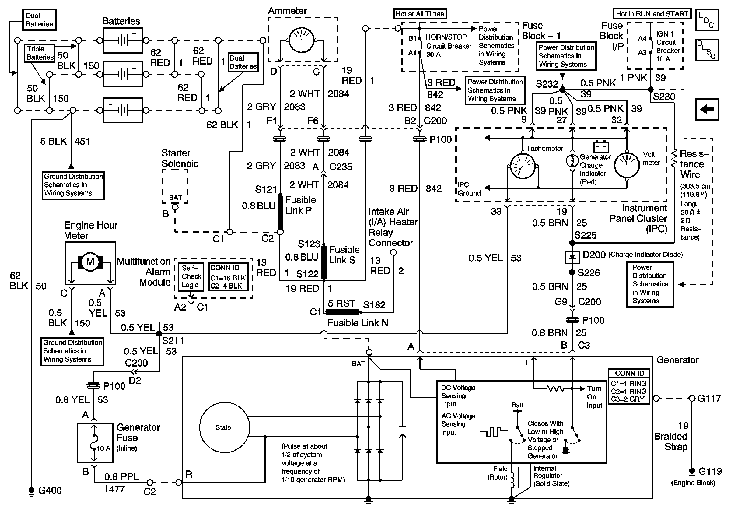
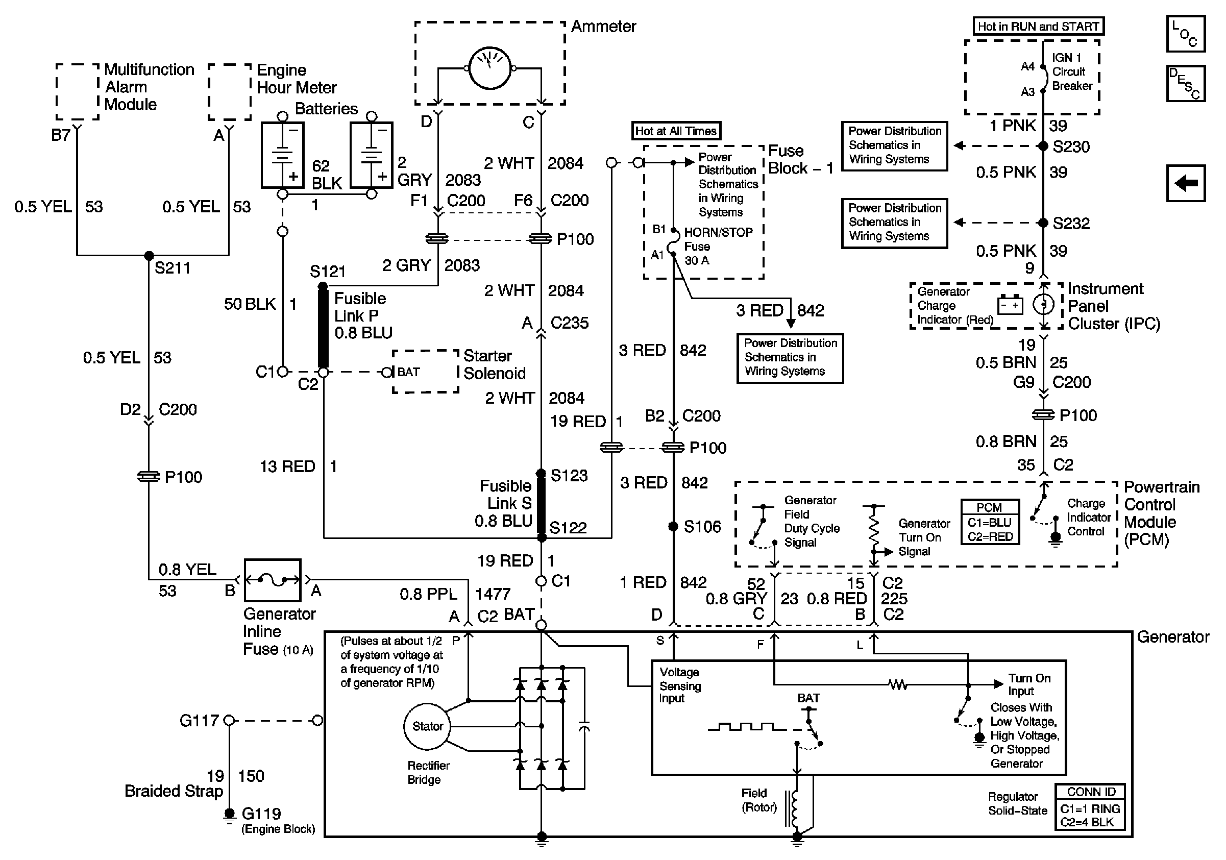
Figure
3:
Charging Circuit LG5
Battery and BRK, HORNS, and STOP LP Circuit Breakers, HD LP SW, HORN/STOP and IGN SW 1 Fuses
Power Distribution Schematics - IGN 1 Circuit Breaker, S232, S243
Master Electrical Component List
Starting System Description and Operation
Ground Distribution Schematics - G100, G101, G103, G107, G117, G119, G120, G121, G124, G400, G401, G405, G412, G413, G414, S170
Battery and BRK, HORNS, and STOP LP Circuit Breakers, HD LP SW, HORN/STOP and IGN SW 1 Fuses
Starting and Charging Schematics - LG5 Starting Circuit (2of2)
Ground Distribution Schematics - S220, S229 LG5
Power Distribution Schematics - IGN 1 Circuit Breaker, S225, S226, S230
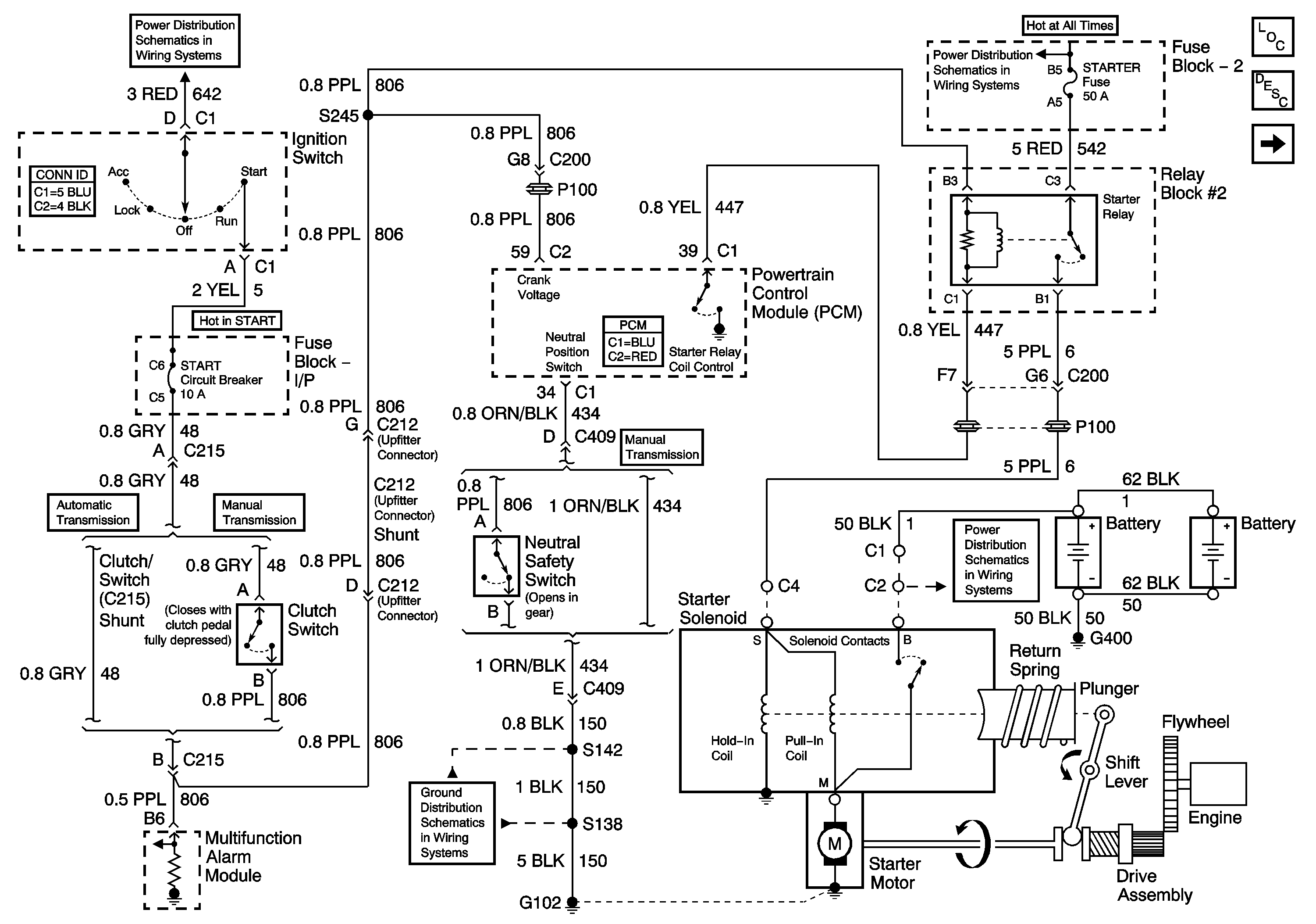
Figure
4:
Starting Circuit L18
Power Distribution Schematics - ACC, B/U, Chassis, ING 1, ING 3 and Start Circuit Breakers
Power Distribution Schematics - Aux 1, Aux 2, ECM, ENG, ETM and Fuel Circuit Breakers, Aux, Body Power 1 and Engine Fuses
Master Electrical Component List
Starting System Description and Operation
Starting and Charging Schematics - L18 Charging Circuit
Ground Distribution Schematics - S142, S178, S179, S405 and S409 L18
Ground Distribution Schematics - G102, and S138 L18
Battery and BRK, HORNS, and STOP LP Circuit Breakers, HD LP SW, HORN/STOP and IGN SW 1 Fuses
Figure
5:
Charging Circuit L18
Power Distribution Schematics - IGN 1 Circuit Breaker, S225, S226, S230
Power Distribution Schematics - IGN 1 Circuit Breaker, S232, S243
Battery and BRK, HORNS, and STOP LP Circuit Breakers, HD LP SW, HORN/STOP and IGN SW 1 Fuses
Master Electrical Component List
Starting System Description and Operation
Starting and Charging Schematics - L18 Starting Circuit