Power Steering Pump Disassemble Hobour BB Series
Removal Procedure
Important:
| • | To ensure correct reassembly, record or mark all information as
specified in the procedure. |
| • | Cap the hose connections. |
Important: The model S205 Hobourn pump is not rebuildable. Repairs should not be
attempted.
- Disconnect the hose connections
- Remove the pump. Refer to
Power Steering Pump Replacement
.
- Clean exterior of pump with solvent.
- Tip the pump to drain oil from the intake tube.
- Rotate the shaft to remove oil from the internal cavities.
- Use the pump mounting bracket or flange to clamp the pump assembly
to a bench vise.
Disassemble Procedure (Pulley Style)
Important: Remove the pulley (27) with an appropriate puller. If a puller
is not available, suspend the pump freely by supporting the pulley rim only
and carefully drive the shaft from the pulley hub. Seat the bolt in the
shaft and tap the bolt head to loosen the pulley and prevent damage to
the shaft.
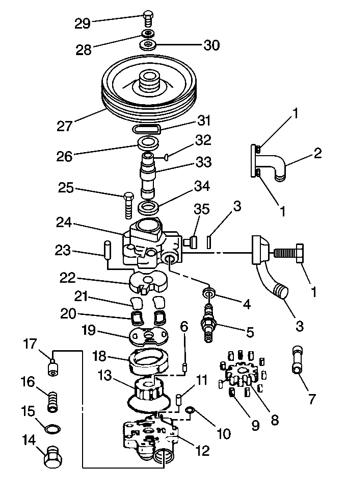
- Remove the following components:
- Remove the key (32) from the shaft (33).
Disassemble Procedure (Gear Style)
- Remove the following components:
- Clean all parts and blow dry.
Disassemble Procedure (Pump)
Important: On flange mounted units, loosen but do not remove the socket head cap
bolts (1) which attach the flange (2) to the pump.
- Disassemble the following components:

- The intake adapter bolt (1).
- The intake adapter (3).
- The intake adapters seal (3).
- Loosen but do not remove valve cap (14).
- Loosen but do not remove the bolts attaching the bracket and/or
pump body to the cover.
- Remove the pump assembly from the vise.
- On flange mounted units (2), remove the flange sealing
gasket and discard.
- Scrape the gasket and sealant from the sealing surfaces.
- Remove the pump body bolts (25).
- Use a suitable block, or pulley, previously removed, loosely placed
onto the pump shaft to steady the pump base for continued disassembly.
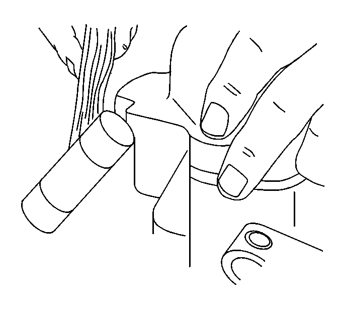
- Pull and gently tap the
bushing cover.
- Remove the bushing cover.

- Remove the following components:
| • | The discharge fitting and seal from the bushing cover (some models) |
| • | The spring (16) and combination (flow control and relief)
valve (17) from the bushing cover). |
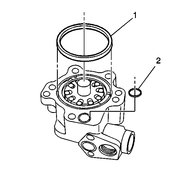
- Remove the seals (1,2).
- Remove the roller vanes from the body pockets.
Disassemble Procedure (Ball Bearing Direct Drive Design)
- Remove the following components:

| 1.4. | The locating pin (23) |
| 1.7. | Slide the parts out of the pump body pocket |
| 1.8. | Leave end plate seals (21,22) in the end plate pockets |
- Remove the shaft bearing sub-assembly (1,2).
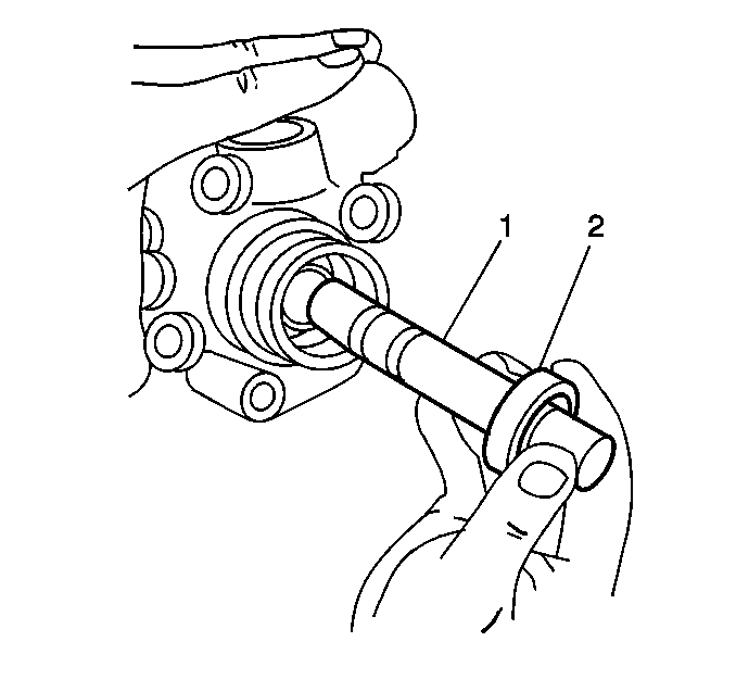

- Remove the seal (34)
from the bushing body (24).
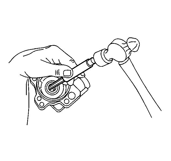
- Use a small punch placed
against the seal from the cam pocket side.
Disassemble Procedure (Bushing Direct Drive Design)
- Remove the carrier (8) and shaft (33) assembly
as a unit. The carrier is restrained from sliding on the shaft by wire snap
rings.

- Mark the position of the locating pin (23), cam (18),
port plate (19), and end plate (22) for reference.
- Remove the following components:
- Slide the parts out of the pump body pocket.
- Remove the seal (34) from the bushing body (24).
- Use a small punch placed against the seal from the cam pocket
side.

Cleaning, Inspection, and Repair Procedure

- Clean all parts with clean
solvent and blow dry.
- Inspect the following components for excessive burning, scoring,
wear or oversize condition:
| | Important: The bushing is not serviceable as a separate component.
|
Maximum bearing bore ID is 40.03 mm (1.5760 in).
| 2.3. | The bushing body (24). |
Replace the bushing body assembly, if necessary.
| 2.4. | The bushing cover (12) |
Replace the bushing cover assembly, if necessary.
| 2.5. | The port plate (19) face for excessive scoring or pitting |
Lapping or polishing of face to remove up to 0.050 mm (0.002 in)
is acceptable. Use care to maintain a flat polished surface.
Replace the shaft if necessary.
| 2.7. | The bearing (26) (some models) for excessive wear and radial
clearance. |
| 2.8. | Measure axial tip with 0.254 mm (0.010 in) maximum
radial clearance. |
| 2.9. | Inspect the seal (34). |
Polished appearance is normal. Wear severe enough to raise a burr on
the ID corner indicates replacement.
| 2.11. | The port plate (19). |
Excessive scoring or galling is not typical. The plate can be hand polished
with the maximum material removal of 0.002 mm (0.0001 in).
Replacement is required for more severe wear.
| 2.12. | The seals (20,21) for cracking or excessive swelling. |
| 2.13. | The end plate (22) for cracks in the area of the sealing
rings. |
| 2.14. | The control valve (17) assembly. |
Faulty internal valve components are difficult to visually determine.
Low pressure may be a sign for valve replacement. The valve must move
smoothly in the valve bore. Minor polishing of the valve OD with the maximum
material removal of 0.002 mm (0.0001 in) is acceptable.
Bearing Replacement
- Disassemble shaft (33) from the bearing (26) using
an arbor press.

Important: Permanent damage will result if the outer race is loaded during the
press operation.
- Assemble shaft (33) to the new bearing (26) using an
arbor press. Support the press load on the inner race only.
Removal Procedure (Carrier)

- Remove the snap ring (31)
near the shaft end.
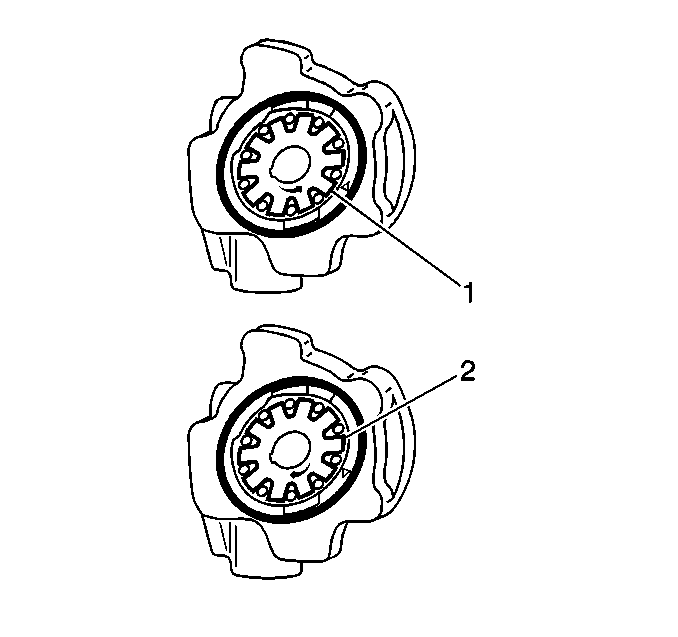
- Note the direction (1,2)
of the teeth before removing the carrier.

- Remove the carrier (8).
- Remove the drive pin (6).
Installation Procedure
- Install the drive pin.

- The new carrier (8).
Install the carrier with the teeth in the correct direction as noted
at removal.
- The snap ring in the groove.
Removal Procedure (Shaft Replacement)
- Remove the snap ring.

Important: Note the direction of the teeth before removing the carrier.
- Remove the carrier (8).
- Remove the drive pin (6).
- Remove the shaft (33).
- Remove the snap ring (some models) from the shaft (33).
Installation Procedure (Shaft replacement)
- Install the following components:

| • | The snap ring (some models) |

- Carrier must be reinstalled
with the teeth in the direction (1,2) as removed.

- Install the following
components:
| • | The snap ring in the groove |
Assembly Procedure (Pump and Shaft)

- Install the new seal (34)
(steel cage side out) into the bushing body (24) assembly.
Using a socket or steel tubing about the size of the seal OD to press
the seal to the bottom of the bore. Use care not to distort the seal case.
- Lubricate the seal (34) and bushing body (24).
- Install the shaft bearing subassembly (26,33) into the
bushing body (24). Do not damage the shaft seal lip.
- Install the snap ring (31).
- Install the seal (21) into the bottom of each kidney shaped
seal gland in the end plate (22).
- Install the square cross-section seal (20) into each gland
on top of the seal (21).
All seals fit tightly to the gland wall.
- Install the end plate (22) with seals (21,20) and
locating pin (23) into the body as noted at the time of disassembly.
- Install the port plate (19).
Align the OD port and the end plate (22).
- Install the cam (18) into the pump body pocket positioned
over the locating pin (23).
- Lubricate the face of the port plate (19), the bushing
body (24), and the ID wall of the cam (18).
Assembly Procedure (Ball Bearing Direct Drive Design)
- Install the drive pin (6) into the shaft (33).

- Install the carrier (8).
The carrier must be reinstalled with the teeth in the direction as noted
at removal.
Assembly Installation Procedure (Bushing Direct Drive Design)
- Lubricate the seal (34) and bushing (24).
- Install the carrier and shaft assembly into the pump body, using
care not to damage the shaft seal lip.
Assembly Procedure
- Install the roller vanes (9) into the carrier (8).

| • | Lubricate the carrier face and shaft. |
| • | Lubricate the cover face and bushing (12). |
- Install the bushing cover (12) to the bushing body (24)
over the shaft (33) and locating pins (23).
| • | Lubricate the valve bore. |
| • | Lubricate the new seal (15). |
- Install the new seal (15) to the valve cap (14).
- Install the valve cap (14) to the valve bore.
Tighten the valve cap finger tight.
- Install the discharge fitting with a new seal, finger tight, to
the bushing cover (some models).
Notice: Use the correct fastener in the correct location. Replacement fasteners
must be the correct part number for that application. Fasteners requiring
replacement or fasteners requiring the use of thread locking compound or sealant
are identified in the service procedure. Do not use paints, lubricants, or
corrosion inhibitors on fasteners or fastener joint surfaces unless specified.
These coatings affect fastener torque and joint clamping force and may damage
the fastener. Use the correct tightening sequence and specifications when
installing fasteners in order to avoid damage to parts and systems.
- Install the pump mounting bracket and/or body to cover retaining
bolts (25).
| • | On direct drive, assemble the flange to the front of the pump
using the bolts or studs and nuts finger tight. Some flanges use face gaskets
or seals. Install a new face gasket or seal at this time. |
| • | Clamp the pump mounting bracket or flange in a bench vise. Do
not distort the sealing surface of the flange mounting. |
Tighten
| • | Tighten the bracket mounting bolts to 48 N·m (35 lb ft).
|
| • | Tighten the valve cap to 65 N·m (48 lb ft).
|
| • | Tighten the discharge fitting to 52 N·m (38 lb ft).
|
- Inspect the shaft (33). The shaft should rotate freely
and smoothly. Maximum turning torque is 1.13 N·m (10 lb ft).

- Install the following components:
| 8.1. | The new seal (3) on the mounting pad of the pump |
| 8.2. | The intake adapter (2) or (3) to pump |
Tighten
Tighten the bolts (1) to 52 N·m (38 lb ft).
| 8.4. | The key (32) in the pump shaft (33). |
| 8.5. | The gear, the washer, and the nut (some models). |
- Replace the pump. Refer to
Power Steering Pump Replacement
.
Power Steering Pump Disassemble Hobourn 600 Series
Repair Procedure
Important: Cap the hose connections.
The model S205 Hobourn pump is not rebuildable. Repairs should not be
attempted.
- Disconnect the hose connections.
- Remove the pump. Refer to
Power Steering Pump Replacement
.
- Carefully clean any dirt or oil from the pump.
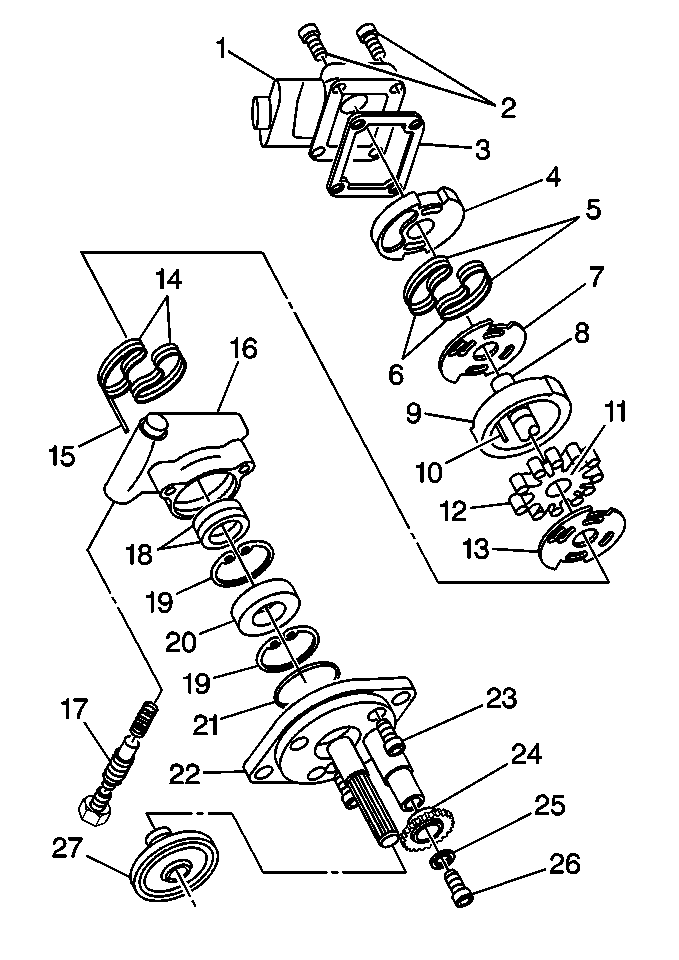
Important: Do not immerse the ball bearing and shaft assembly in any solvent. Carefully
wipe oil, grease and dirt from the shaft and bearing.
Handle all parts very carefully while washing and air drying.
Carefully separate all parts and place on a clean and well lighted area
for inspection.
- Remove the following components:
| • | The bolt (26) , washer (25) and gear (24)
if equipped |
| • | The mounting plate bolts (23) |
| • | The mounting plate (22) |
| • | The discharge adapter spring and valve assembly (17) |
| • | The pump cover bolts (2) |
| • | The endplate (4) and the port plate (7) |
| • | The carrier (11) and rollers (12) |
| • | The carrier drive pin (10) from the shaft |
| • | The locating pin (15) from the pump body (16) |
| • | The cam ring (9) from the pump body (16) |
| • | The port plate (13) from the pump body (16) |
| • | The shaft bearing assembly (8,20) from the pump body (16) |
| • | The seals (18) from the pump body (16) |
Inspection Procedure
Important: Clean with care using cleaning solvent. Leave in a clean place to dry.
- Begin the inspection procedure when all parts are present and
correct .

- Check for contamination.
- Inspect discharge adapter (17) for the following conditions.
| • | Damage to the cross hole on the orifice |
- If there is damage to any of the components, replace the flow
valve assembly.
- Inspect the following for burrs, excessive wear, or contamination:
- If there is any damage to any of the components, replace the cam
assembly.
- Inspect the valve (17) for free movement.
- If there is no movement, replace the flow control valve assembly (17).
- Inspect the port plates (7,13) for scoring and excessive
wear.
Important: Light polishing marks on the port plate are normal and acceptable.
- If there is damage to the plates (7,13), replace the plates.
- Inspect the drive shaft (8) and splines for wear.
- If there is wear, replace the shaft bearing kit.
- Inspect the cover (22) for damaged threads.
- If the threads are damaged, replace the cover kit.
- Check valve bore (16) and by-pass hole for scoring.
- If there is any damage, replace the pump assembly.
- In order to remove the bearing (20) from the shaft, proceed
as follows.
Important: The spline shaft pumps use two snap rings (19). Gear driven
pumps use one snap ring (19) .
- Remove the snap ring (19) from the shaft.
- Remove the bearing (20) from the shaft using a press.
- Remove the rear snap ring (19) from the shaft.
Assembly Procedure
Notice: When adding or making a complete fluid change, always use GM P/N
10500179 or equivalent meeting GM Spec. No. 9985010 power steering fluid.
Failure to use the proper fluid will cause seal damage and fluid leaks.

- Assemble the new oil seals (13)
in the pump body as follows:
| 1.1. | Install the orange seal (18) into the pump body with the
seal lip facing the pump bushing. |
| 1.2. | Install the brown seal (18) over the orange seal with the
seal lip facing the opposite direction. |
- Install a seal thin-wall protective cover over the shaft.
- Install shaft and bearing assembly through the pump body .
- Seat the bearing (20) into the pump housing (16)
with a press.
- Check the drive shaft for free rotation.
- Mount the pump body (16) into a suitable fixture with the
shaft facing up.
- Install new O-rings (14) into the pump body.
- Install new backup sealing rings (14).
- Install the port plate (13) with the timing grooves facing
down.
- Insert the locating pin (15) on the right hand side for
counter-clockwise rotation.
- Install the cam ring (7) over the locating pin with the
arrow pointing in the clockwise direction.
- Remove the protective cover from the shaft.
- Install the carrier drive pin (10) onto the shaft keyway,
applying a small amount of grease on the pin.
- Install the carrier (11) onto the shaft (8) and
engage the drive pin (10).
- Install the rollers (12) into the slots of the carrier (11).
- Apply a small amount of specified fluid to the top of the carrier.
- Install the port plate (7) on top of the carrier (11).
- Install new O-rings (5) into the end plate (4).
- Install new backup sealing rings (6).
- Install the endplate (4) onto the drive shaft (8).
- Install the body to cover (3) gasket with the yellow side
to the top.
Notice: Use the correct fastener in the correct location. Replacement fasteners
must be the correct part number for that application. Fasteners requiring
replacement or fasteners requiring the use of thread locking compound or sealant
are identified in the service procedure. Do not use paints, lubricants, or
corrosion inhibitors on fasteners or fastener joint surfaces unless specified.
These coatings affect fastener torque and joint clamping force and may damage
the fastener. Use the correct tightening sequence and specifications when
installing fasteners in order to avoid damage to parts and systems.
- Install the cover (1) and cover to body bolts (2)
Tighten
Tighten the bolts to 20-27 N·m (17-19 lb ft).
- Tighten the bolts progressively and as diagonal pairs.
- Check the shaft for free rotation.
- Install spring and valve (17) into the valve bore.
- Install new discharge adapter O-ring.
- Check the valve for free movement.
Tighten
Tighten the discharge adapter to 60-67 N·m (45-48 lb ft).
- Install a new body-to-mounting plate O-ring (21).
- Install the mounting plate (22) with the bolts (23).
Tighten
Tighten the bolts to 20-27 N·m (17-19 lb ft).
- On pumps using a gear drive, proceed as follows:
| 30.1. | Install the gear (24). |
| 30.2. | Install the washer (25). |
| 30.3. | Check the valve for free movement. |
Tighten
Tighten the discharge adapter to 60-67 N·m (45-48 lb ft).
| 30.4. | Install a new body-to-mounting plate O-ring (21). |
| 30.5. | Install the mounting plate (22) with the bolts (23). |
Tighten
Tighten the bolts to 20-27 N·m (17-19 lb ft).
- Install the pump. Refer to
Power Steering Pump Replacement
.
- Bleed the power steering system. Refer to
Power Steering System Bleeding
.


