- Center the following components:
- Remove the Pitman arm. Refer to
Pitman Arm Replacement
in Steering Linkage
(Non-Rack and Pinion).
- Remove the cardan joint pinch bolt.
- Remove the cardan joint.
- Slide the intermediate shaft up until the joint clears the steering
gear stub shaft.
- Loosen the lock nut.
- Turn the Pitman shaft preload adjuster clockwise in order to complete
the following actions:
| • | Relieve the over-center preload. |
| • | Provide a clearance between the sector gear and the worm ball
nut. |
- Perform the following procedures to disconnect the power steering
hoses at the pump:
| 8.1. | Cap the hoses in order to prevent any dirt from entering the system. |
| 8.2. | Tag the power steering hose locations. |
| 8.3. | Ensure that the engine is off. |
| 8.4. | Turn the stub shaft to the right and the left until the gear stops
draining. |
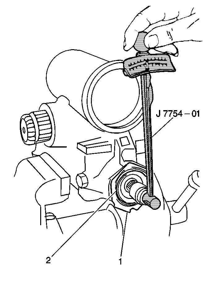
- Use the following steps
in order to obtain a reading:
| 9.1. | Place the J 7754-01
with a 3/4 inch twelve point socket on the stub shaft. |
| 9.2. | Move the J 7754-01
at a constant speed and through a 90 degree arc. |
| 9.3. | Take readings 90 degrees from the stop. Record the readings. |
Repeat the above procedure several times in order to obtain an average
reading.
| 9.4. | The worm shaft thrust bearing preload should be 0.7-1.3 N·m
(6-12 lb in). |
| 9.5. | Any rough or lumpy action may be due to bearing damage. In this
case, remove and repair the steering gear. Refer to
Steering Gear Replacement
. |
- Loosen the adjuster plug (2) lock nut (1).
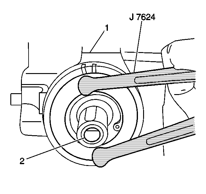
- Use the J 7624
in order to turn the adjuster plug (2)
clockwise until the plug and the worm shaft bearing are firmly bottomed.
This will require about 27 N·m (20 lb ft)
of torque.
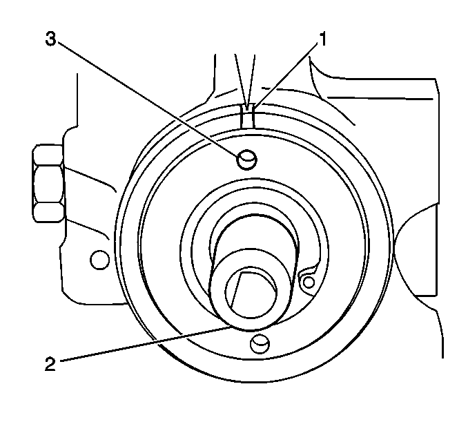
- Mark the housing in line
with one of the adjuster plug holes (2).
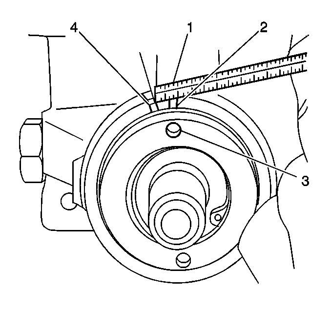
- Measure 13 mm (1/2 in)
counter-clockwise.
Mark the housing again (4).
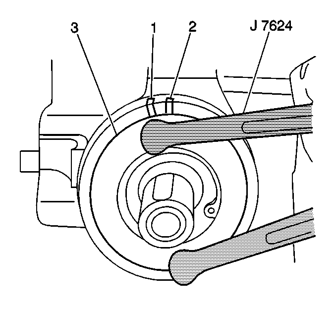
- Rotate the adjuster plug (3) until the adjuster plug hole is aligned
with the second mark (2).

Notice: Use the correct fastener in the correct location. Replacement fasteners
must be the correct part number for that application. Fasteners requiring
replacement or fasteners requiring the use of thread locking compound or sealant
are identified in the service procedure. Do not use paints, lubricants, or
corrosion inhibitors on fasteners or fastener joint surfaces unless specified.
These coatings affect fastener torque and joint clamping force and may damage
the fastener. Use the correct tightening sequence and specifications when
installing fasteners in order to avoid damage to parts and systems.
- Hold the adjuster
plug (2) in place.
Install the adjuster plug lock nut (1).
Tighten
Tighten the adjuster plug lock nut to 109 N·m (80 lb ft).
- If necessary, repeat the procedure in order to achieve the proper
preload.
If the proper worm shaft bearing preload cannot be achieved, replace
the steering gear. Refer to
Steering Gear Replacement
.
- When the worm shaft bearing is properly adjusted, adjust the Pitman
shaft over-center preload. Refer to
Steering Gear Pitman Shaft Over-Center Preload Adjustment - Off Vehicle
.


