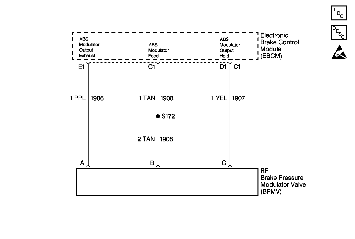
Circuit Description
The red diagnostic status lamps latches on to indicate a permanent or intermittent open or short circuit in the solenoids of one of the four modulators or the wiring connecting it to the system.
Conditions for Illuminating Diagnostic Status Lamps
| • | Open in modulator valve solenoid or modulator valve wiring |
| • | Short in modulator valve solenoid or modulator valve wiring |
Action Taken When Diagnostic Status Lamps Illuminate
| • | The ABS indicator lamp is illuminated. |
| • | The ABS is disabled. |
Conditions for Clearing Diagnostic Status Lamps
| • | Repair the condition responsible for illuminating status lamps. |
| • | Reset the EBCM (see Diagnostic Status Lamps). |
Diagnostic Aids
An intermittent malfunction may be caused by a poor connection, rubbed through wire insulation, or a wire that is broken inside the insulation. If the RIGHT, FRONT and MOD diagnostic status lamps are on only during moist environmental changes (rain, snow, vehicle wash), all modulator valve circuitry should be thoroughly inspected for signs of water intrusion. Use the following procedure. Spray the suspected are with a 5 % salt water solution (two teaspoons of salt to 12 oz. of water). Test drive the vehicle over various road surfaces (bumps, turns, etc.) above 24 km/h (15 mph) for at least 30 seconds. If condition returns, replace suspected harness.
Any circuitry that is suspected of causing the intermittent complaint should be thoroughly checked for backed out terminals, improper mating, broken locks, improperly formed or damaged terminals, poor terminal to wiring connections or physical damage to the wiring harness.
When inspecting a modulator valve, inspect the sensor terminals and harness connector for corrosion and/or water intrusion. If evidence of corrosion or water intrusion exists, replace the modulator valve. Refer to Front Brake Pressure Modulator Valve Replacement .
Test Description
The number(s) below refer to the step number(s) on the diagnostic table.
-
This test checks for the correct resistance of the modulator valve exhaust solenoid circuit (including wiring). This test also checks for a short to ground in the modulator valve circuitry.
-
This test checks for the correct resistance of the modulator valve hold solenoid circuit (including wiring).
Step | Action | Value(s) | Yes | No |
|---|---|---|---|---|
1 | Were you sent here from the Diagnostic System Check? | -- | Go to Step 2 | |
2 |
Is the connector OK? | -- | Go to Step 3 | Go to Step 9 |
Using a J 39200 , measure the resistance between terminal C1 and terminal E1 of the EBCM connector. Is the resistance measured within the specified range? | 3.5-5 ohms | Go to Step 4 | Go to Step 6 | |
Using a J 39200 , measure the resistance between terminal C1 and terminal D1 of the EBCM connector. Is the resistance measured within the specified range? | 3.5-5 ohms | Go to Step 5 | Go to Step 7 | |
5 | Using a J 39200 , measure the resistance between terminal C1 of the EBCM connector and ground. Is the resistance measured equal to the specified value? | OL | Go to Step 8 | Go to Step 13 |
6 |
Is the resistance measured within the specified range? | 3.5-5 ohms | Go to Step 11 | Go to Step 10 |
7 |
Is the resistance measured within the specified range? | 3.5-5 ohms | Go to Step 12 | Go to Step 10 |
8 |
Did the ABS indicator lamp turn on and stay on? | -- | Go to Step 14 | Go to Diagnostic Aids |
9 | Repair the EBCM connector. Refer to Connector Repairs in Wiring Systems. Is the repair complete? | -- | -- | |
10 | Replace the right front modulator valve. Refer to Front Brake Pressure Modulator Valve Replacement . Is the repair complete? | -- | -- | |
11 | Repair open or high resistance in CKT 1906 or CKT 1908. Refer to Wiring Repairs in Wiring Systems. Is the repair complete? | -- | -- | |
12 | Repair open or high resistance in CKT 1907 or 1908. Refer to Wiring Repairs in Wiring Systems. Is the repair complete? | -- | -- | |
13 | Repair short to ground in CKT 1906, CKT 1907 or CKT 1908. Refer to Wiring Repairs in Wiring Systems. Is the repair complete? | -- | -- | |
14 | Replace the EBCM. Refer to Electronic Brake Control Module Replacement . Is the repair complete? | -- | -- |
