Cranking Circuit
The cranking system consists of the following components:
| • | The ignition switch (The engine control switch on diesel vehicles) |
| • | Related electrical wiring |
| • | A neutral start switch (on vehicles with automatic transmissions) |
| | Vehicles equipped with an electronically-controlled automatic transmission
do not have a separate neutral start switch in the cranking circuit. The neutral
switch is built into the Vehicle Interface Module (VIM). Refer to
Engine Electrical Components
for
component location. Refer to the following sections for detailed circuit
description: |
PG-260 Starter Motor
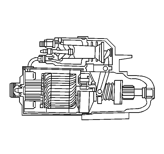
The PG-260 starter motor
is used on the 7.4L gasoline engines. The PG-260 has a gear reduction
ration of 5:1 through the planetary gears. The PG-260's small size and light
weight offers improved cranking performance and reduced current requirements
for larger gasoline engines.
37-MT Starter Motors

The 37-MT/300 and
the 37-MT/350 starter motors are used on the 7.2L diesel engines. The
above starter motors have the following components:
| • | Adjustable drive end frame housings |
| | The oil soaked wicks provide lubrication from the bronze bushings. |
| • | An external grounding stud (37-MT/350 only) |
| | The external grounding stud is installed in the field frame in place
of one of the pole shoe screws. |
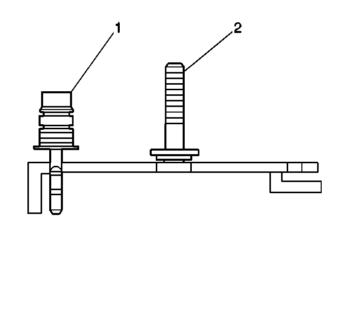
The optional 37-MT/350 starter motor (RPO-KQR) for the 7.2L
is equipped with built-in overcrank protection. If overcranking occurs, the
built-in thermostat will open and stop the cranking cycle in order to protect
the starter motor.
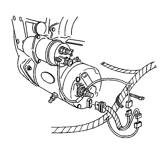
After the starter motor cools, the thermostat will close and engine
cranking can resume. The engine usually cools in 1 to 6 minutes.
Shift Lever and Solenoid Plunger
The following starter motors have an enclosed shift lever:
The shift lever mechanism and solenoid plunger are located within the
drive housing. The drive housing protects the above components from exposure
to the following conditions:
The starter solenoid operates when the ignition of the engine control
switch turns to the START position (automatic transmission in the NEUTRAL
position). the main contacts close with the starter solenoid energized. Closing
the main contacts completes the electrical circuit between the battery and
the starter motor. Energizing the solenoid also shifts the plunger and the
shift lever. Shifting the plunger and the shift lever engages the pinion gear
to mesh with the engine flywheel ring gear. This enables cranking.
When the engine starts, the pinion overrunning clutch protects the armature
from excessive speed. Releasing the ignition or engine control switch opens
the solenoid main contacts and causes the plunger's return spring to disengage
the pinion. In order to prevent damage to the starter, release the key immediately
after the engine starts.
37-MT Starter Motors
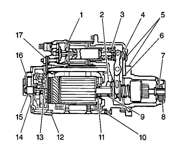
The 37-MT 300 and the
37-MT 350 heavy-duty starter motors have totally enclosed shift levers (4)
and solenoid plungers (3) in order to protect the shift levers and
solenoid plungers from the following conditions:
A seal between the shaft and the shift lever housing and a rubber boot
or linkage seal (3) over the solenoid plunger prevent oil entry into
the motor main frame and the solenoid case. The prevention of oil entry allows
the motor to operate on wet clutch applications.
Other seals are used in order to resist entry of dirt and moisture into
the motor assembly. when the oil reservoirs and seals are included, the motor
is classified as long life, and will provide long periods of attention-free
operation.
Oil-saturated wicks (2) provide lubrication to each of the three
sintered bronze bushings (8,9, and 15). The oil-saturated wicks are
in contact with the outside of each bushing. Oil soaks into the sintered
bronze material in order to lubricate the bearing surface of the armature
shaft. The oil supply is long lasting. It is not necessary to add oil to
the wicks between engine overhauls.
The action of the solenoid moves the heavy-duty 5-roll drive assembly
into mesh with the ring gear. The pinion remains engaged until the release
of the engine control (ignition) switch interrupts the solenoid circuit.
The pinion overruns when the engine starts to reduce the possibility of damage
to the starter.
Type 300 starter motors have a grounding terminal installed in the commutator
end frame. Type 350 starter motors have this terminal in addition to a grounding
stud installed into the field frame in place of one of the pole shoe screws.
Refer to
Starter Motor Replacement
for views of the wiring connections to the
starter motor.
Type 350 starter motors have overcrank protection. The motor has a built-in
thermostat that opens the circuit to the solenoid terminal if the motor gets
to hot. This action stops the cranking cycle. After the motor cools, the
thermostat closes and the motor can be cranked again. The motor will usually
cool in one to six minutes.
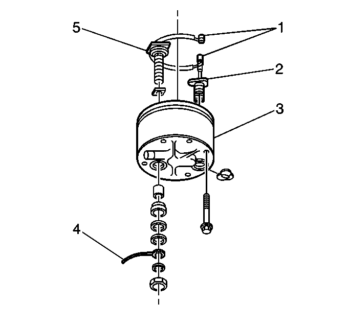
Internally, the thermostat (2) attaches to the commutator end
ground terminal lead (4).
Under normal conditions, no maintenance is required between engine overhaul
periods. Perform the following procedures at the time of overhaul:
| • | Disassemble the starter motor. |
| • | Inspect the starter motor. |
| • | Clean the starter motor. |
| • | Test the starter motor. |
37-MT Adjustable Drive Housing
The drive housing attaches to the lever housing by screws that are located
around the outside of the housing. Perform the following procedures in order
to relocate the housing:
In this assembly, the lever housing and the commutator end frame are
attached to the field frame by screws in the field frame.
37-MT Starter Motor Identification
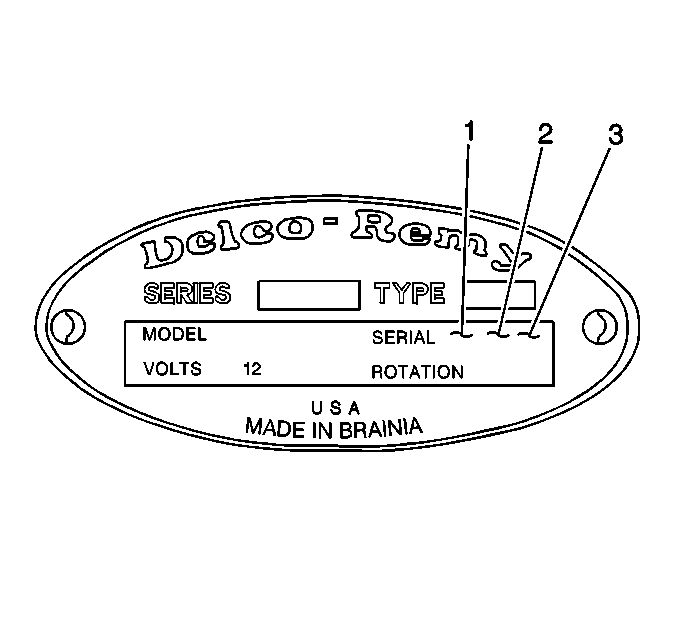
The build date uses the
following format:
The month is shown in alpha form; January is A, February is B, etc.
Therefore, the identification code 96L12 is 1996, December 12.
37-MT Armature Identification
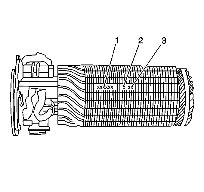
The build date is stamped
on the lamentations near the part number (1). The build date uses the
following format:
A96 is January 1996.
37-MT Drive Assembly Identification
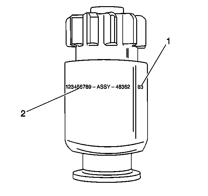
The build date (1)
is stamped on the outer shell near the part number (2). The build date
uses the following format:
The month appears in alpha form; A 96 is January 1996.
37-MT Solenoid Identification
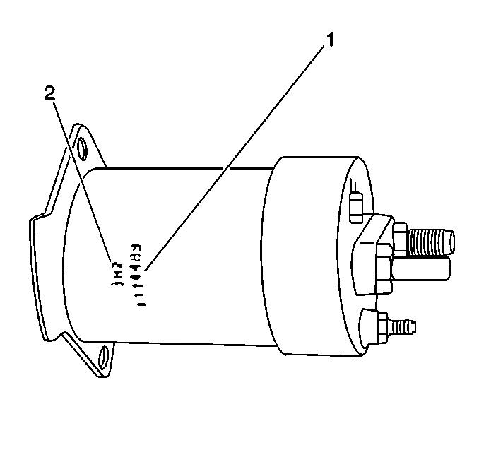
The build date (2)
is stamped on the solenoid in the following format:
The month appears in alpha form; A 96 is January 1996. Therefore 6 K
18 is 1996 November 18.


