Tools Required
| • | J 7079-2 Universal Driver Handle - Non-Threaded |
| • | J 8092 Universal Driver Handle - 3/4 in - 10 |
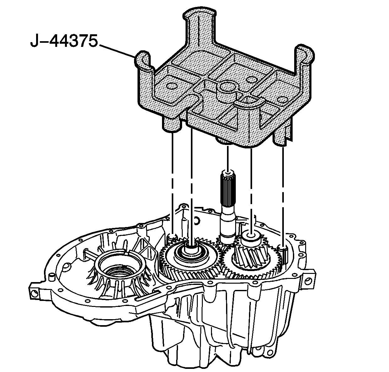
| • | J 44375 Assembly Pallet |
| • | J 44376 Bearing Pusher/Puller |
| • | J 44377 Input Shaft Anti-Rotation Tool |
| • | J 44381 Shifter Bearing/Input and Output Bearing Remover |
| • | J 44383 Countershaft Bearing Installer |
| • | J 44385 Differential Bearing Race and Seal Installer |
| • | J 44387 Output Shaft Bearing Sleeve Installer and Pin |
| • | J 44389 Countershaft Bearing Installer |
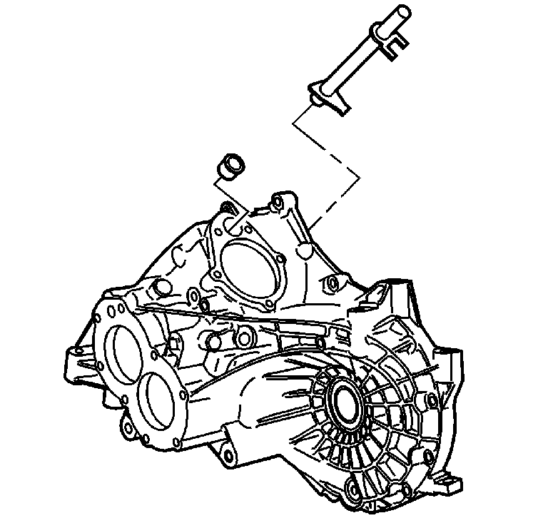
- Install the shift rod and bushing.
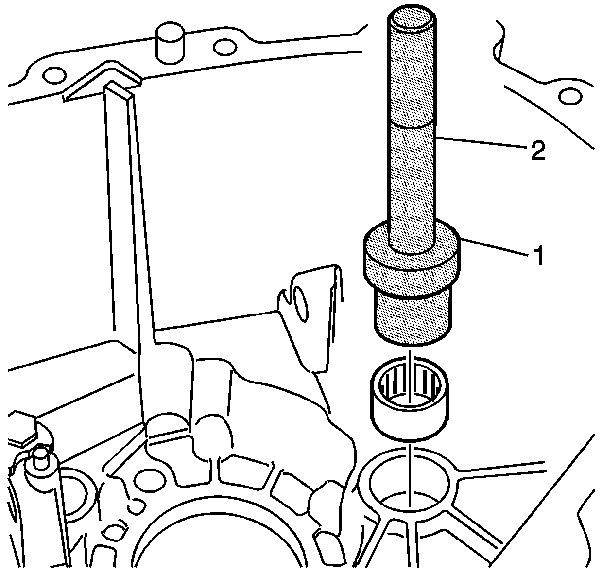
- Install the intermediate shaft needle bearing to the transmission housing using the J 44383 (1) and the J 8092 (2).
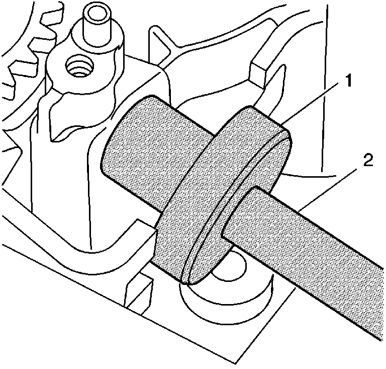
- Install a new shifter shaft bearing flush with the casting in the transmission housing, using the J 44381 (1) and the J 8092 (2).
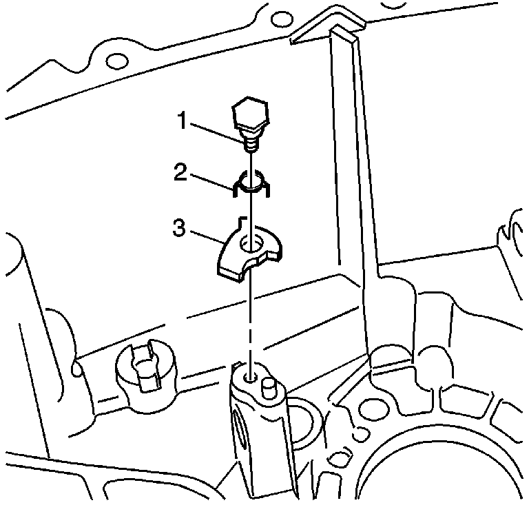
- Apply GM P/N United States 12345382, GM P/N Canada 10953489 to the reverse lockout lever bolt threads.
- Install the reverse lockout lever (3), spring (2), and the bolt (1) to the transmission housing, if equipped.
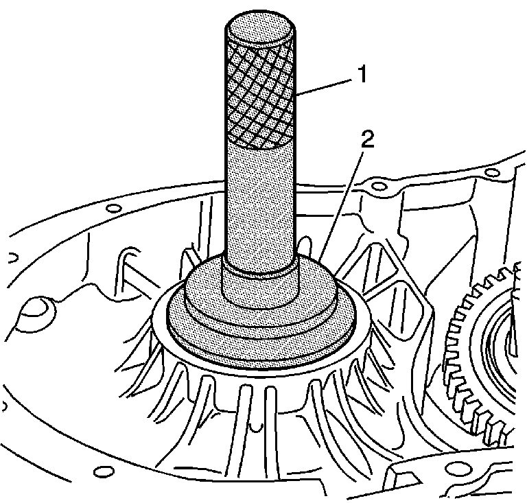
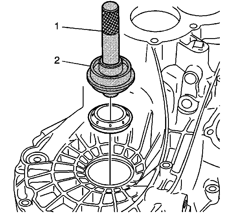
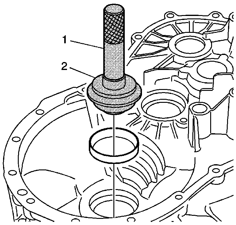
- Install a new differential bearing race to the transmission housing using theJ 44385 (2) and the J 7079-2 (1).
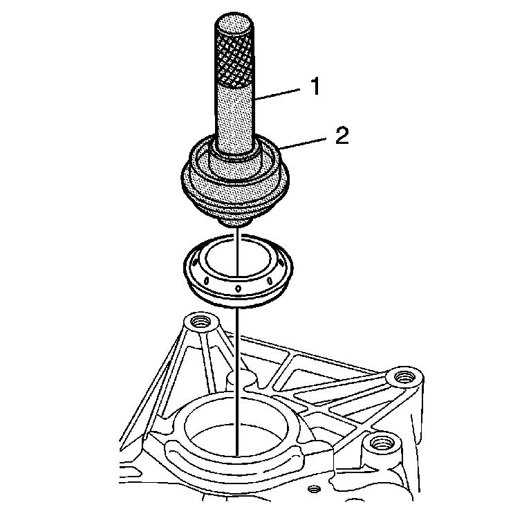
- Install a new differential side bearing race seal to the transmission housing using the J 44385 (2) and the J 7079-2 (1).
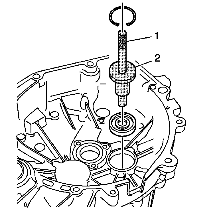
- Install the countershaft bearing to the clutch housing using the J 44381 (1) and the J 7079-2 (2).
- Install a new snap ring.
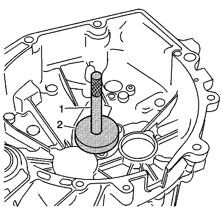
- Install the input shaft bearing to the clutch housing using the J 44381 (2) and the J 7079-2 (1).
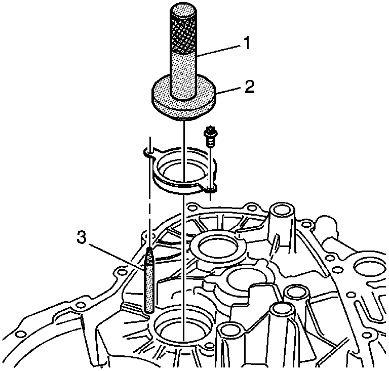
- Install the output shaft bearing race and bolts using the J 44387-1 (2), J 44387-2 (3), and the J 7079-2 (1).
- Install a new differential bearing race to the clutch housing using the J 44385 (2) and the J 7079-2 (1).
- Install a new differential output shaft seal to the clutch housing using theJ 44385 (2) and the J 8092 (1).
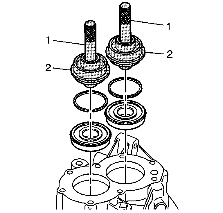
- Install the snap rings to the input shaft and output shaft bearings.
- Install the input shaft and output shaft bearings into the transmission housing using the J 44385 (2) and the J 7079-2 (1).
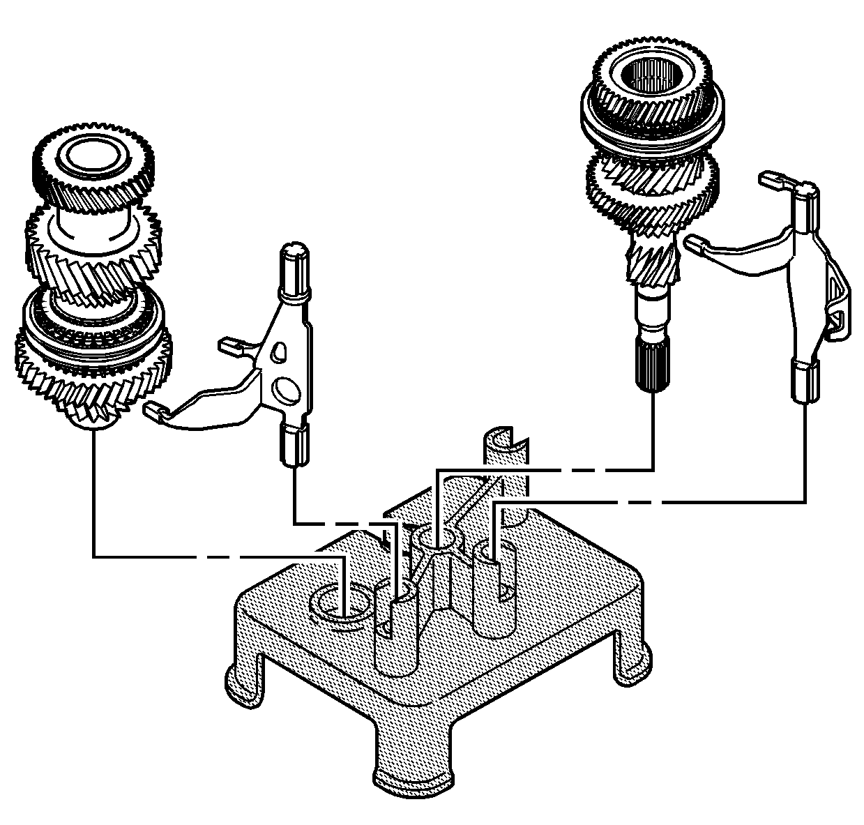
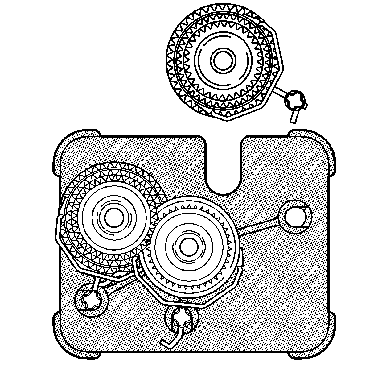
- Install the shift forks and the input shaft and output shaft onto the J 44375 .
- Install the countershaft and the shift fork onto the J 44375 .
- Rotate the shaft to verify all gears are properly meshing.
- Install the housing onto the shift forks and the shafts on to the J 44375 . Line up the shift forks and the shafts with the housing.
- Install the transaxle case to the shafts using the J 44376 .
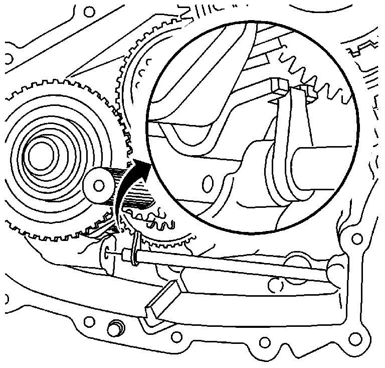
- Shift the transmission into 4th and 5th gear using a screwdriver in an upward direction.
- Apply GM P/N United States 12345493, GM P/N Canada 10953488 to the input and output shaft bolts.
- Install NEW input and output shaft bolts while holding the transmission into 4th and 5th gear in an upward direction.
- Install sealant GM P/N United States 12346286, GM P/N Canada 10953472 to the rear cover.
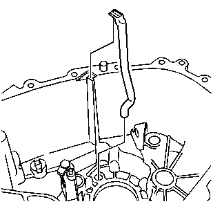
- Install the oil guide.
- Install the rear cover.
- Install the rear cover bolt.
- Apply sealant GM P/N United States 12346004, GM P/N Canada 10953480 to the backup lamp switch.
- Install the backup lamp switch into the transaxle case.
- Turn the transaxle case and the J 44375 over on the table.
- Remove the J 44375 from the gear shafts and the shift forks.
- Install the oil tube into the transaxle case.
- Install the shift rod to the shift fork.
- Apply sealer GM P/N United States 12378516, GM P/N Canada 88900757 to the transaxle case to shifter cover mating surface.
- Install the shifter and the shifter retaining bolts.
- Shift the transmission into neutral.
- Apply GM P/N United States 12346004, GM P/N Canada 10953480 to the shifter guide bolt.
- Install the shifter guide bolt.
- Install the differential into the transaxle case.
- Install the roller bearing onto the output shaft.
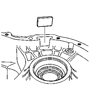
- Install the magnet into the transaxle case.
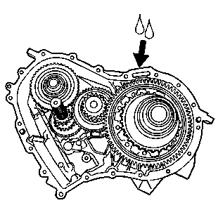
- Apply sealant GM P/N United States 12378516, GM P/N Canada 88900757 to the transaxle case to clutch housing mating surface.
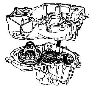
- Install the clutch housing to the transaxle case.
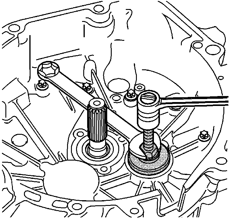
- Install the countershaft into the clutch housing bearing using the J 44389 .
- Install the clutch housing to transaxle case bolts.
- Turn the transmission over.
- Install the transaxle case to clutch housing bolts.
- Turn the transmission so the shifter is on top.
- Shift the transmission into any gear.
- Install the input shaft seal to the actuator.
- Install the actuator and tube.
- Install the actuator and tube bolts.
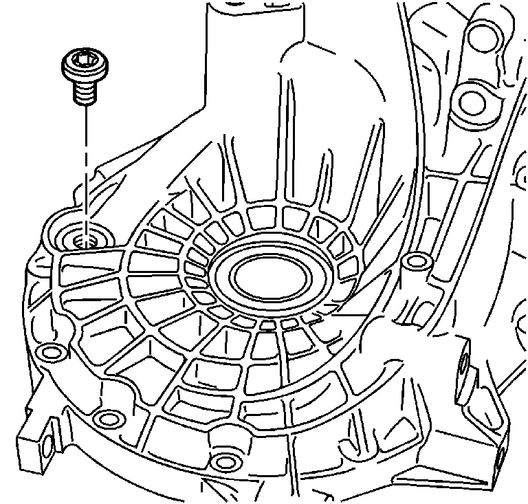
- Apply GM P/N United States 12346004, GM P/N Canada 10953480 to the transmission drain plug.
- Install the transmission drain plug.
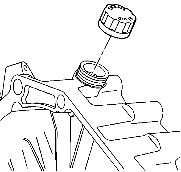
- Install the transmission fill cap.
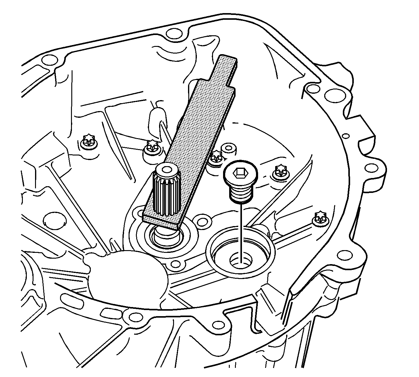
- Hold the input shaft with the J 44377 .
- Apply GM P/N United States 12345493, GM P/N Canada 10953488 to the intermediate shaft bolt.
- Install the bolt in the intermediate shaft.
- Install a new plastic oil guide into the intermediate shaft.
- Install a new intermediate shaft sealing cap.
- Apply GM P/N United States 12345382, GM P/N Canada 10953489 to the vehicle speed sensor bolt.
- Install the vehicle speed sensor, seal, and bolt.
- Install the shift cable bracket (4), the isolators (3), the spacers (2) and the bolt (1).
Important: Do not over apply the threadlocker to the bolt threads.
Notice: Use the correct fastener in the correct location. Replacement fasteners must be the correct part number for that application. Fasteners requiring replacement or fasteners requiring the use of thread locking compound or sealant are identified in the service procedure. Do not use paints, lubricants, or corrosion inhibitors on fasteners or fastener joint surfaces unless specified. These coatings affect fastener torque and joint clamping force and may damage the fastener. Use the correct tightening sequence and specifications when installing fasteners in order to avoid damage to parts and systems.
Important: The spring (2) fingers must be positioned on either side of the lever (3).
Tighten
Tighten the bolt to 6 N·m (53 lb in).
Tighten
Tighten the output shaft bearing bolts to 10 N·m
(89 lb in).
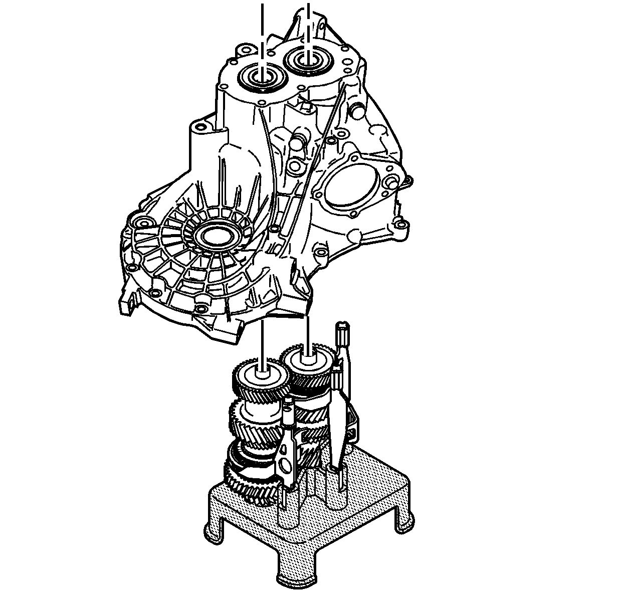
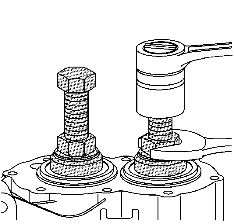
Important: Install the transaxle case to the shafts evenly using the J 44376 .
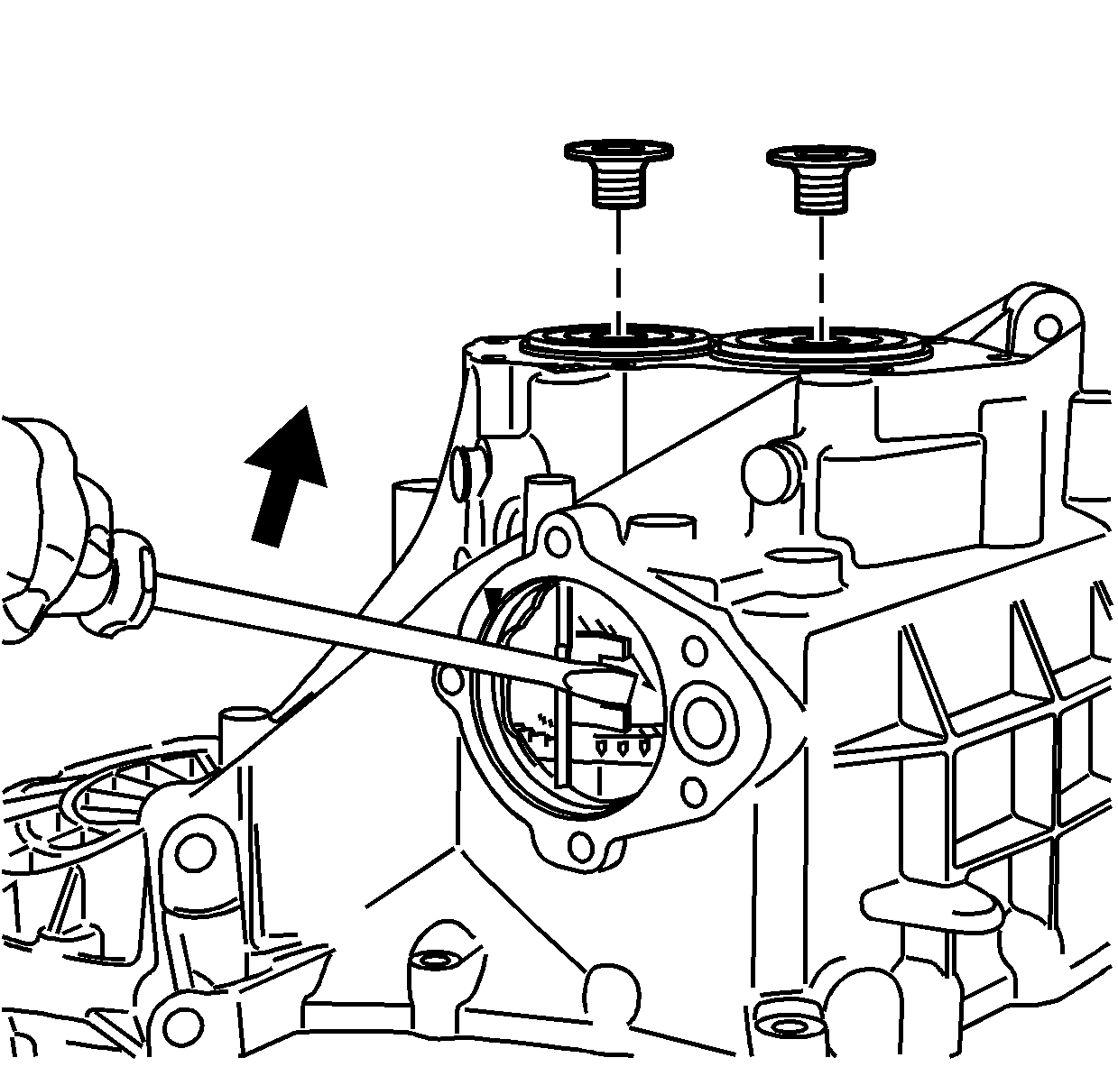
Tighten
Tighten the shaft bolts to 110 N·m
(81 lb ft).
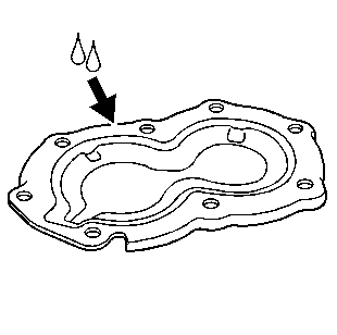
Important: If shimming is required, refer to Shimming Procedures before installing the cover.
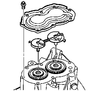
Important: The oil guide only installs in one direction. Ensure the oil guide is completely seated in the gear shafts.
Tighten
Tighten the rear cover bolt to 25 N·m
(18 lb ft).
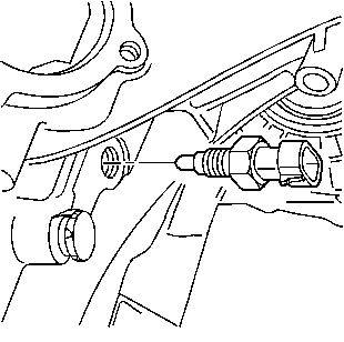
Tighten
Tighten the backup lamp switch to 18 N·m
(13 lb ft).
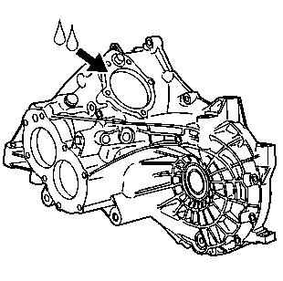
Important: Use only the approved sealer for the transaxle case to shifter cover mating surface.
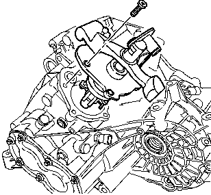
Tighten
Tighten the shifter retaining bolts to 25 N·m
(18 lb ft).
Install all possible shifter bolts with the shifter in the neutral position. Install the last shifter bolt in gear and then shift the transmission back into neutral.
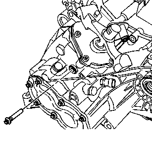
Notice: Hand start and tighten the shifter guide bolt to avoid damaging the shift lever.
Tighten
Tighten the shifter guide bolt to 25 N·m
(18 lb ft).
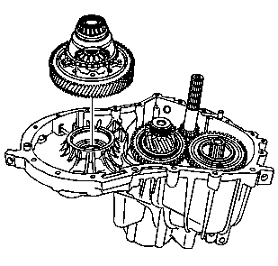
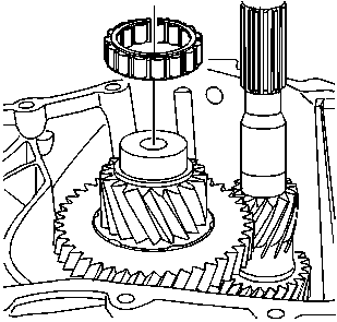
Important: The step in the roller bearing faces opposite of the pinion gear.
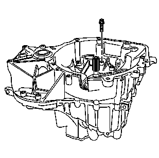
Tighten
Tighten the housing bolts to 27 N·m
(20 lb ft).
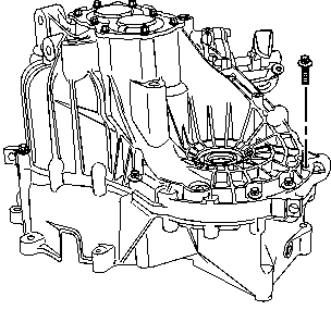
Tighten
Tighten the housing bolts to 27 N·m
(20 lb ft).
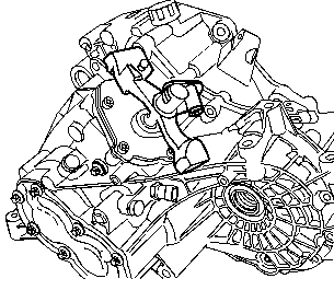
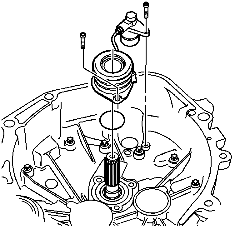
Tighten
Tighten the tube bolts to 10 N·m (89 lb in).
Tighten
Tighten the transmission drain plug to 38 N·m
(28 lb ft).
Tighten
Tighten the intermediate shaft bolts to 95 N·m
(70 lb ft).
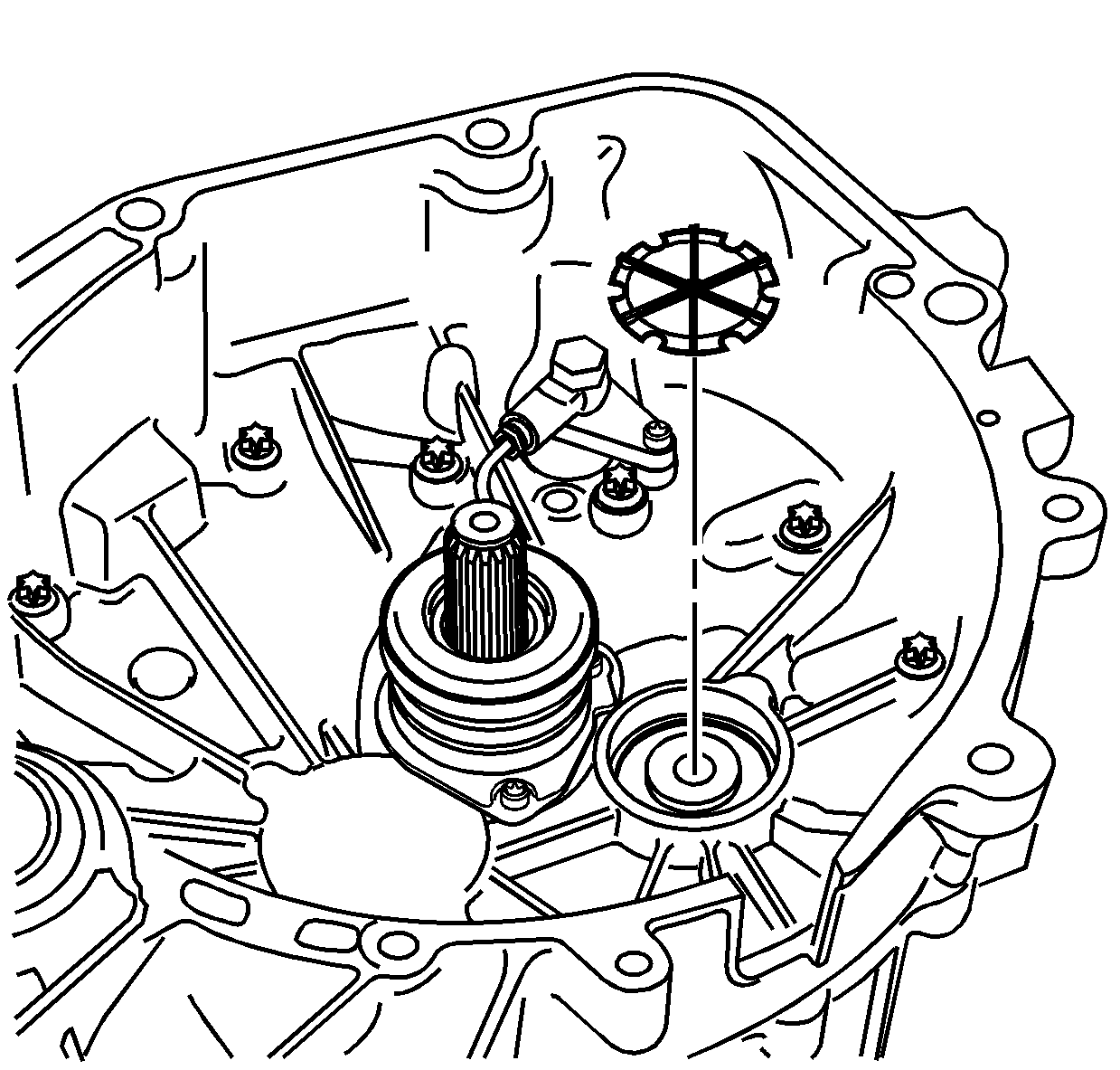
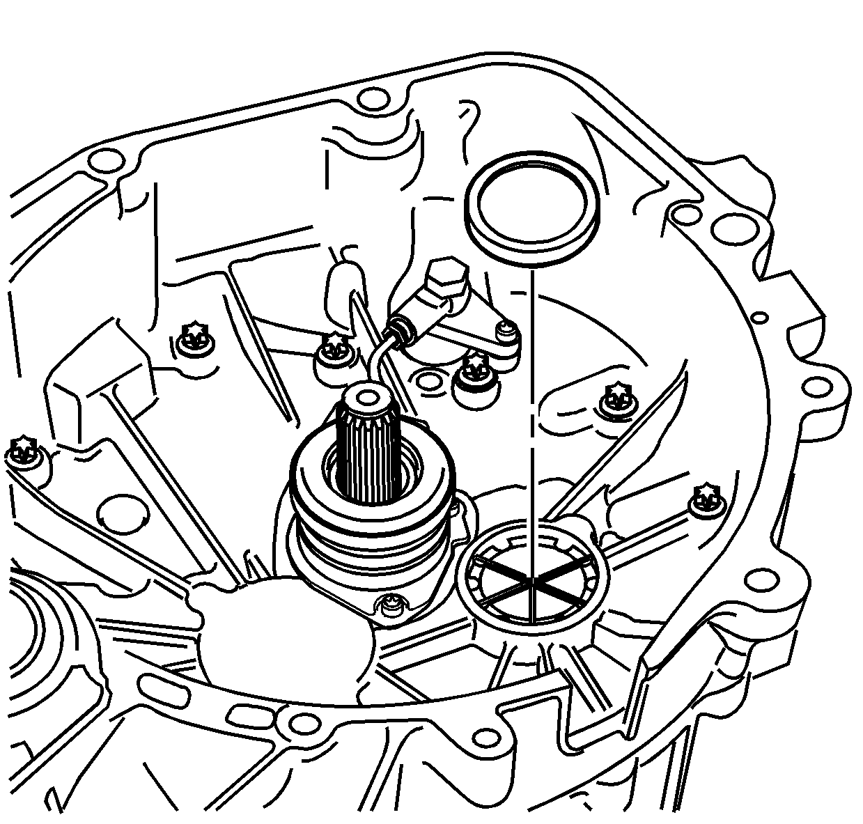
Important: Ensure not to press the sealing cap past the bottom of the chamfer.
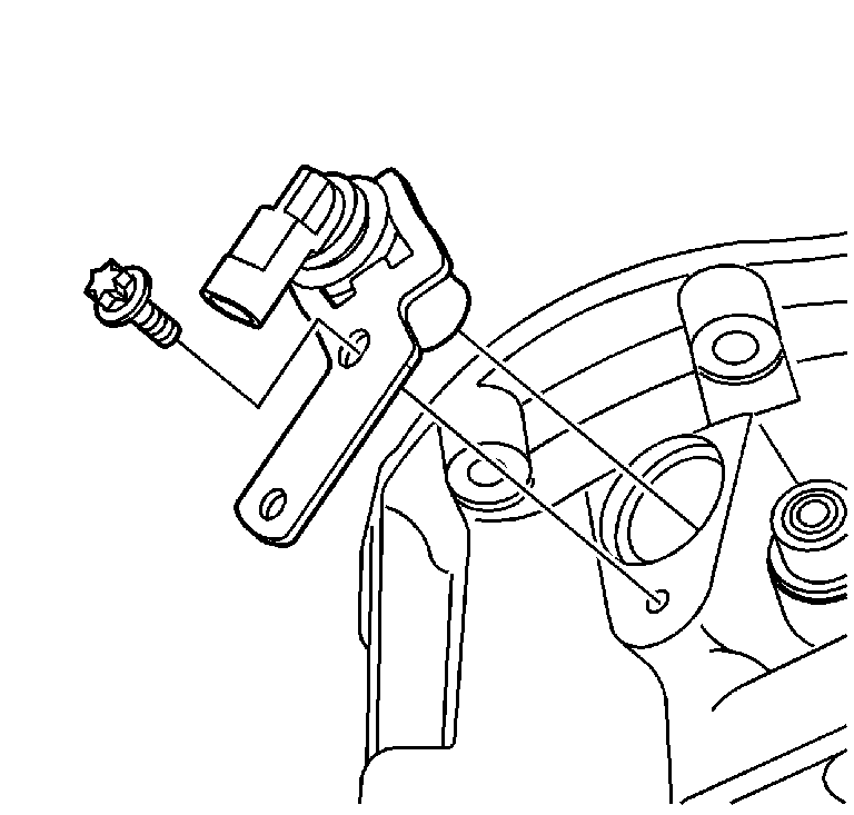
Tighten
Tighten the bolt to 12 N·m (8 lb ft).
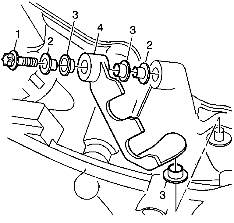
Tighten
Tighten the shift cable bracket bolt to 20 N·m
(15 lb ft).
