For 1990-2009 cars only
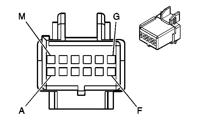
| Table 1: | Instrument Panel Cluster (IPC) |
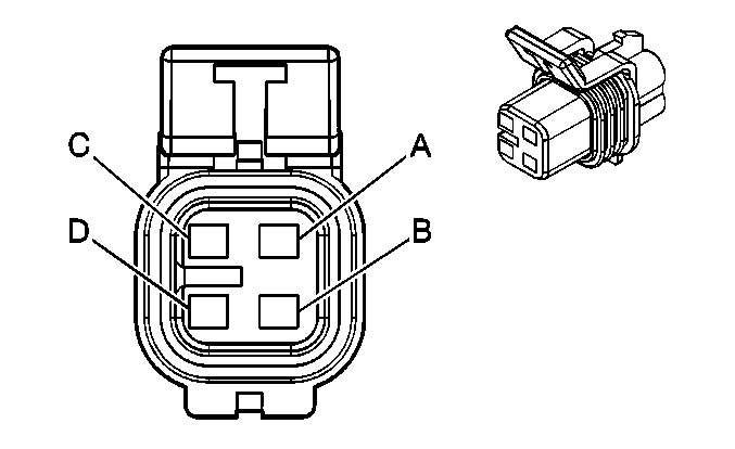
| Table 2: | Fuel Pump And Sender Assembly |

| |||||||
|---|---|---|---|---|---|---|---|
Connector Part Information |
| ||||||
Pin | Wire Color | Circuit No. | Function | ||||
A | BLK | 150 | Ground | ||||
B | GRY | 8 | Instrument Panel Lamp Supply Voltage | ||||
C | DK BLU | 15 | Right Turn Signal Lamps Supply Voltage | ||||
D | BRN/WHT | 419 | MIL Control | ||||
E | GRY | 728 | Security Indicator Control | ||||
F | LT BLU | 14 | Left Turn Signal Lamps Supply Voltage | ||||
G | ORN | 1440 | Battery Positive Voltage | ||||
H | BLK/WHT | 451 | Ground | ||||
J | PNK | 39 | Ignition 1 Voltage | ||||
K | PPL | 1807 | Class 2 Serial Data | ||||
L | PPL | 1807 | Class 2 Serial Data | ||||
M | -- | -- | Not Used | ||||

| |||||||
|---|---|---|---|---|---|---|---|
Connector Part Information |
| ||||||
Pin | Wire Color | Circuit No. | Function | ||||
A | PPL | 1589 | Fuel Level Sensor Signal | ||||
B | GRY | 120 | Fuel Pump Supply Voltage | ||||
C | BLK | 150 | Ground | ||||
D | BLK/WHT | 2759 | Low Reference | ||||
