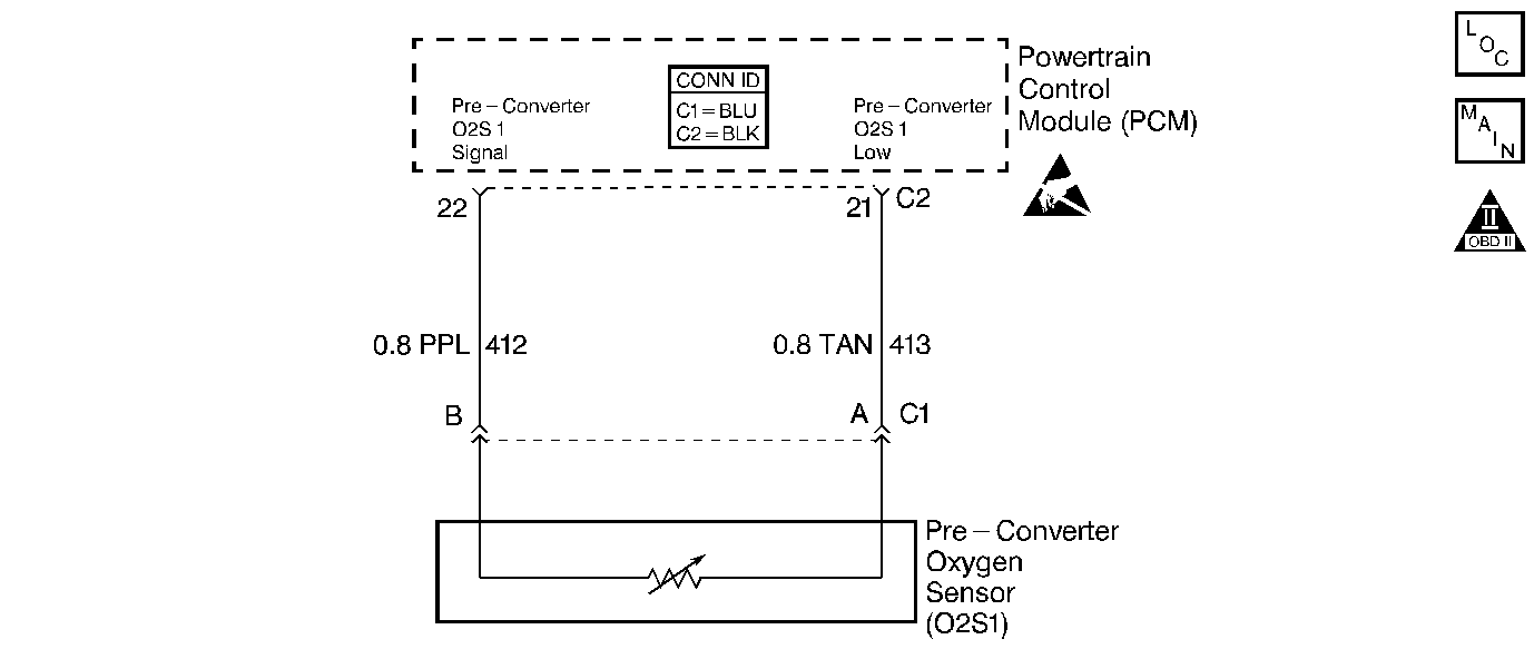
Circuit Description
The Powertrain Control Module (PCM) supplies a voltage of about 0.45 volt between the Oxygen Sensor (O2S 1) signal and the ground circuit. The Oxygen Sensor (O2S 1) varies the voltage within a range of about 1 volt if the exhaust is rich, down through about 0.10 volt if the exhaust is lean.
The sensor is like an open circuit and produces no voltage when below 315°C (600°F). An open sensor circuit or a cold sensor causes an Open Loop operation.
Replace the entire oxygen sensor (O2S 1) assembly (Do not attempt to repair the oxygen sensor) if the following conditions exist:
| • | Damaged wiring |
| • | Damaged electrical connector |
| • | Damaged terminal(s) |
Conditions For Running The DTC
| • | DTCs P0105, P0107, P0108, P0112, P0113, P0117, P0118, P0122, P0123, P0171, P0201, P0202, P0203, P0204, P0300, P0335, P0440.P0442, P0446, P0506, P0507, P0601, P0602, or P1441 not set. |
| • | Air flow is more than 3 grams per second. |
| • | Engine Coolant Temperature (ECT) is more than 70°C (158°F). |
| • | Throttle Position (TP) angle is between 8 percent and 56 percent for 20 seconds. |
| • | Engine run time is more than 30 seconds. |
Conditions For Setting The DTC
O2S 1 voltage is between 399 mV and 499 mV for 125 seconds.
Action Taken When the DTC Sets
| • | The Malfunction Indicator Lamp (MIL) will illuminate after two consecutive ignition cycles in which the diagnostic runs with the fault active. |
| • | The PCM will record the operating conditions at the time that the diagnostic fails. This information will store in the Freeze Frame and Failure Records buffers. |
| • | A history DTC stores. |
| • | The coolant fan turns ON. |
| • | The vehicle will operate in an Open Loop operation. |
Conditions for Clearing the MIL/DTC
| • | The MIL will turn OFF after three consecutive ignition cycles in which the diagnostic runs without a fault. |
| • | A history DTC will clear after 40 consecutive warm up cycles without a fault. |
| • | Use a scan tool to clear the DTCs. |
Diagnostic Aids
The normal scan tool voltage varies between 150 mV to 850 mV (0.15 volt to 0.85 volt) while in a Closed Loop operation.
An intermittent could be the result of the following conditions:
| • | Poor electrical connection |
| • | Rubbed through wire insulation |
| • | Broken wire inside of the insulation |
Inspect for a poor electrical connection or a damaged harness. Inspect the harness electrical connectors for the following conditions:
| • | Improper mating |
| • | Broken locks |
| • | Improperly formed electrical connectors |
| • | Damaged terminals |
| • | A poor terminal to wire connection |
| • | A damaged harness |
Test Description
The numbers below refer to the step numbers on the diagnostic table:
-
When the system is operating correctly the HO2S voltage should toggle above and below the specified values.
-
The specified value is what is measured on a correctly operating system.
-
The specified value is what is measured on a correctly operating system.
-
This vehicle is equipped with a PCM which utilizes an Electrically Erasable Programmable Read Only Memory (EEPROM). When the PCM is replaced, the new PCM must be programmed.
Step | Action | Value(s) | Yes | No | ||||||
|---|---|---|---|---|---|---|---|---|---|---|
1 | Did you perform the Powertrain On-Board Diagnostic (OBD) System Check? | -- | ||||||||
|
Important: If any other DTCs are set, except HO2S DTCs, refer to other DTCs first before proceeding with this table.
Does scan tool indicate O2 voltage varying outside the specified values? | 400-500 mV | |||||||||
3 | Operate vehicle within Fail Records conditions. Does the scan tool indicate this DTC failed this ignition? | -- | Go to Diagnostic Aids | |||||||
4 | Inspect and test for the following:
Did you find and correct the condition? | -- | ||||||||
Does the voltage measure near the specified value? | 450 mV | |||||||||
Does the scan tool indicate O2 voltage at or near the specified value? | 0 mV | |||||||||
7 | Test the low circuit for an open or high resistance. Refer to Circuit Testing and Wiring Repairs in Wiring Systems. Did you find and correct the condition? | -- | ||||||||
8 | Test the signal circuit for an open or high resistance. Refer to Circuit Testing and Wiring Repairs in Wiring Systems. Did you find and correct the condition? | -- | ||||||||
9 | Test for poor connections at the O2. Refer to Testing for Intermittent Conditions and Poor Connections and Connector Repairs in Wiring Systems. Did you find and correct the condition? | -- | ||||||||
10 |
Important: Determine the cause of contamination before replacing the sensor. Inspect and test for the following:
Replace the effected O2 sensor. Refer to Oxygen Sensor Replacement . Did you complete the repair? | -- | -- | |||||||
11 | Test for poor connections at the PCM. Refer to Testing for Intermittent Conditions and Poor Connections and Connector Repairs in Wiring Systems. Did you find and correct the condition? | -- | ||||||||
|
Important: The replacement PCM must be programmed. Refer to Powertrain Control Module Replacement . Replace the PCM. Did you complete the repair? | -- | -- | ||||||||
13 |
Does the DTC reset? | -- | ||||||||
14 | Use the scan tool in order to check for DTCs. Does the scan tool indicate any DTCs that you have not diagnosed? | -- | System OK |
