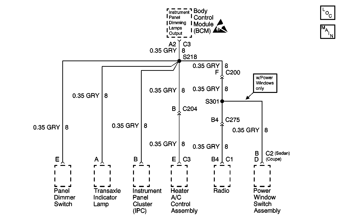
Circuit Description
The body control module (BCM) receives a variable voltage from the instrument panel lamp dimmer switch. The BCM uses this signal in order to vary the illumination level of the instrument panel lamps. The instrument panel dimming lamps output is the variable supply voltage used to light the instrument panel lamps. If a malfunction occurs in the instrument panel dimming lamps circuit, this DTC is set.
Conditions for Running the DTC
The park lamp input is active (park or headlamps on).
Conditions for Setting the DTC
Any of the following conditions will set this DTC:
| • | The instrument panel dimming lamps output is open for 125 milliseconds. |
| • | The instrument panel dimming lamps output is shorted to ground for 125 milliseconds. |
| • | The instrument panel dimming lamps output is shorted to battery positive voltage for 125 milliseconds. |
Action Taken When the DTC Sets
| • | If the instrument panel dimming lamps output is open, the instrument panel lamps will not illuminate. |
| • | If the instrument panel dimming lamps output is shorted to ground, the instrument panel lamps will not illuminate. |
| • | If the instrument panel dimming lamps output is shorted to battery positive voltage, the instrument panel lamps will illuminate at full intensity. |
Conditions for Clearing the DTC
| • | A current DTC B2625 will clear when the malfunction is no longer present and the ignition switch is cycled. |
| • | All BCM history codes clear after 100 ignition cycles with no current codes active during the 100 ignition cycles. |
Diagnostic Aids
If the DTC is a history DTC, the malfunction may be intermittent. Try performing the tests while wiggling the wires and connectors. This may often cause the malfunction to appear.
Test Description
The number(s) below refer to the step number(s) on the diagnostic table.
Step | Action | Yes | No |
|---|---|---|---|
1 | Did you perform the Lighting Systems Diagnostic System Check? | Go to Step 2 | |
2 | Test for an open, short to ground or short to voltage in the panel dimming lamps output circuit between the body control module and splice S218. Refer to Circuit Testing and Wiring Repairs in Wiring Systems. (Turn the ignition on when testing for a short to voltage.) Did you find and correct the condition? | Go to Step 9 | Go to Step 3 |
3 | Test for a short to ground or a short to voltage between splice S218 and each individual component connected to the instrument panel dimming lamps output. Refer to Circuit Testing and Wiring Repairs in Wiring Systems. (Turn the ignition on when testing for a short to voltage.) Did you find and correct the condition? | Go to Step 9 | Go to Step 4 |
4 | Inspect for poor connections at the harness connector of the body control module. Refer to Testing for Intermittent Conditions and Poor Connections and Connector Repairs in Wiring Systems. Did you find and correct the condition? | Go to Step 9 | Go to Step 5 |
5 | Inspect for poor connections at the harness connector of each component. Refer to Testing for Intermittent Conditions and Poor Connections and Connector Repairs in Wiring Systems. Did you find and correct the condition? | Go to Step 9 | Go to Step 6 |
Did this DTC set as current when one of the components was reconnected? | Go to Step 7 | Go to Step 8 | |
7 | Replace the component which causes this DTC to be set as current. Refer to the appropriate repair procedure. Did you complete the replacement? | Go to Step 9 | -- |
8 |
Important: Perform the setup procedure for the body control module. Refer to Body Control Module (BCM) Programming/RPO Configuration . Replace the body control module. Refer to Body Control Module Replacement in Body Control System. Did you complete the replacement? | Go to Step 9 | -- |
9 |
Does the DTC reset? | Go to Step 2 | System OK |
