Third Clutch Pressure Switch

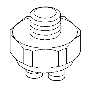
Wired in series with the TCC electrical circuit, this switch is normally open. The third clutch pressure switch is closed in third gear by third clutch fluid to complete the TCC circuit. This allows the TCC to apply in third gear only.
Torque Converter Clutch Solenoid

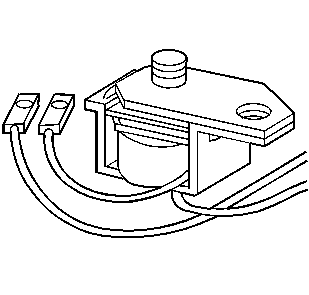
The torque converter clutch (TCC) solenoid is an electrically controlled exhaust valve. When energized by the Control Module (PCM), it shuts off exhausting solenoid signal fluid at the converter clutch control valve. The closing of the solenoid valve causes the solenoid signal fluid pressure to increase and shift the converter clutch control valve. This applies the torque converter clutch.
Park/Neutral Position Switch

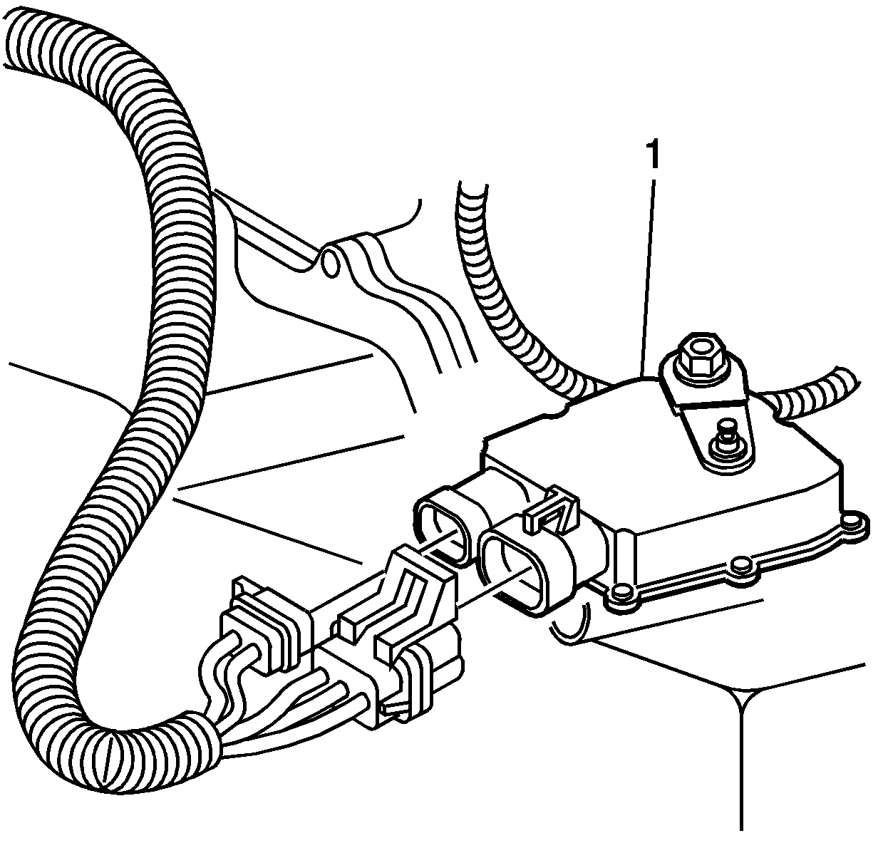
The Transmission Range (TR) Switch is part of the Park/Neutral Position (PNP) and Back-up Lamp Switch Assembly (1), which is externally mounted on the transmission manual shaft. The TR switch contains four internal switches that indicate the transmission gear range selector lever position. The PCM supplies ignition voltage to each switch circuit. By grounding one or more of the switch circuits, the PCM detects the selected gear range by the state change of the switch input. Refer to Transmission Range Switch Logic . Switch input to the PCM is represented on the scan tool as HI and LOW. HI indicates an ignition voltage signal. LOW indicates a zero voltage signal. The four parameters represent transmission range switch signal A,B,C and P.
Vehicle Speed Sensor (VSS) Assembly

The vehicle speed sensor (VSS) assembly is a magnetic inductive pickup that produces an AC voltage. The voltage is sent to the PCM where it is used to calculate vehicle speed and control the apply and release of the torque converter clutch (TCC).
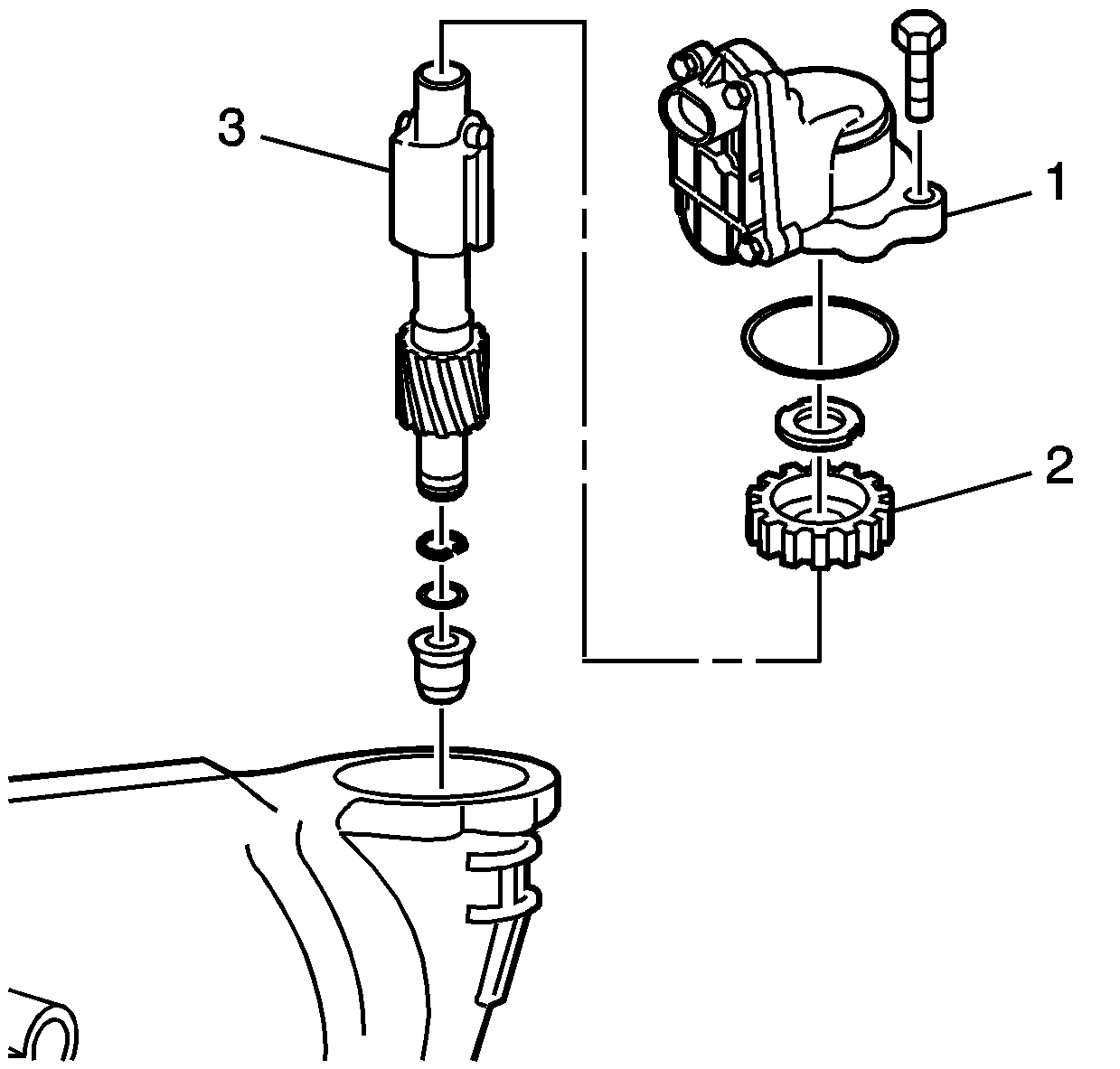
The VSS assembly (1) mounts to the transmission case directly above the governor assembly (3). A rotor (2) attached to the governor assembly is driven by the transmission differential carrier. A slight air gap is maintained between the VSS and the rotor teeth. The sensor consists of a metal core surrounded by a coil of wire and a permanent magnet. As the differential carrier rotates the governor assembly, the rotor teeth break the magnetic field, producing AC voltage. The higher the vehicle speed, the greater the pulse, the higher the AC voltage.
The AC voltage levels vary from a minimum of 0.5 volts AC at 25 RPM to more than 100 volts AC at 200 RPM. VSS resistance should be 139-376 ohms.
