Tools Required
| • | J 36005 Rear
Crankshaft Seal Installer |
Removal Procedure
- Disconnect the negative battery cable. Refer to
Battery Negative Cable Disconnection and Connection
in Engine Electrical.

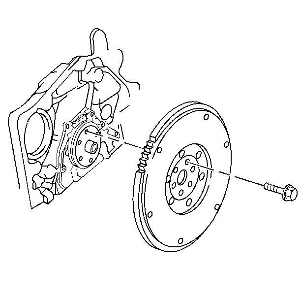
- Remove the flywheel. Refer
to
Engine Flywheel Replacement
in
Engine Mechanical.

- Remove the oil pan to
the crankshaft seal housing bolts.
- Remove the seal housing to block bolts.
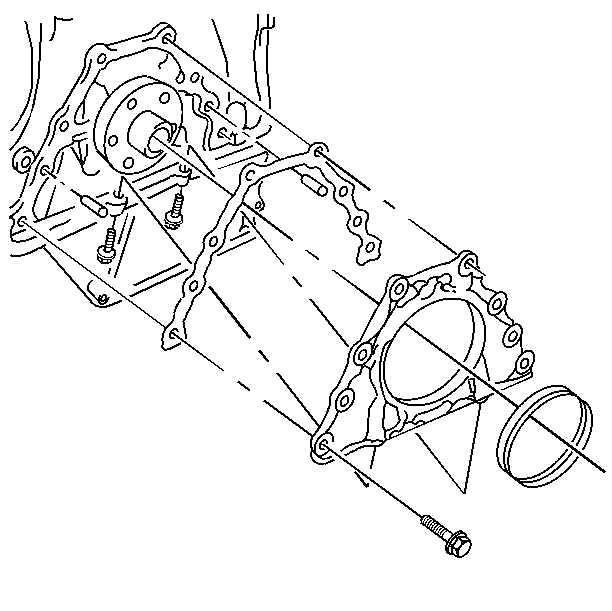
- Remove the seal housing and gasket.
Notice: Properly support the seal housing to prevent damage to the seal during
removal. Damage to the seal will result in an oil leak.
- Support the seal housing for the seal removal using two
wood blocks of equal thickness. With the wood blocks on a flat surface, position
the seal housing and the blocks so that the transmission side of
the seal housing is supported across the dowel pin and center bolt
holes on both sides of the seal opening.
- Drive the crankshaft seal evenly out of the transmission side
of the seal housing using a small chisel in the relief grooves on the crankshaft
side of the seal housing.
Installation Procedure

- Replace the oil pan gasket
if any of the following conditions exist:
| • | Separation from the aluminum carrier |
- Inspect the strips of silicone across the top of the aluminum
carrier at the oil pan, at the cylinder block, and at the seal housing three
way joint.
- If these strips are damaged they may be repaired using Silicone
Sealant GM P/N 12345739 (Canadian P/N 10953541) or equivalent.
Use only enough sealant to restore the silicone strip to its original
dimension.
- Install seal into housing using the following steps:
| • | Lightly grease seal lip. |
| • | Tap seal into housing using plastic hammer, make sure seal seats
in housing. |
Notice: Use the correct fastener in the correct location. Replacement fasteners
must be the correct part number for that application. Fasteners requiring
replacement or fasteners requiring the use of thread locking compound or sealant
are identified in the service procedure. Do not use paints, lubricants, or
corrosion inhibitors on fasteners or fastener joint surfaces unless specified.
These coatings affect fastener torque and joint clamping force and may damage
the fastener. Use the correct tightening sequence and specifications when
installing fasteners in order to avoid damage to parts and systems.
- Install the oil pan to the seal housing bolts.
Tighten
Tighten the bolts to 12 N·m (106 lb in).

- Install the flywheel.
Refer to
Engine Flywheel Replacement
in Engine Mechanical.
- For vehicle equipped with a manual tranmission, install the clutch
and pressure plate and clutch cover assembly. Refer to
Clutch Pressure and Driven Plate Replacement
in Clutch.
- Install the transmission assembly. Refer to
Transmission Replacement
in Manual Transmission - M5 and M86,
or
Transmission Replacement
in Automatic
Transaxle-4T40 - E/4T45 - E.
- Connect the negative battery cable. Refer to
Battery Negative Cable Disconnection and Connection
in Engine Electrical.
- Start the engine.


