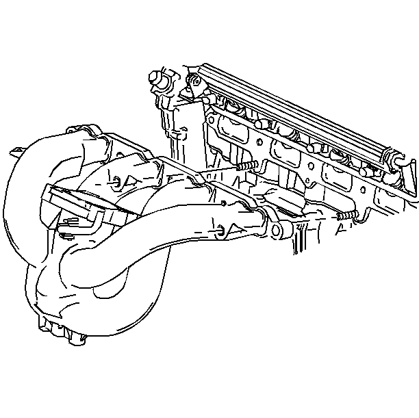
Important: The engine and the manifold should be at ambient temperature when assembled.
Do not attempt to install a cold manifold on a hot engine.

- Install the intake manifold
and the gasket. If the gasket is damaged, install a new one with the stamped
numbers facing towards the manifold surface.

Notice: Use the correct fastener in the correct location. Replacement fasteners
must be the correct part number for that application. Fasteners requiring
replacement or fasteners requiring the use of thread locking compound or sealant
are identified in the service procedure. Do not use paints, lubricants, or
corrosion inhibitors on fasteners or fastener joint surfaces unless specified.
These coatings affect fastener torque and joint clamping force and may damage
the fastener. Use the correct tightening sequence and specifications when
installing fasteners in order to avoid damage to parts and systems.
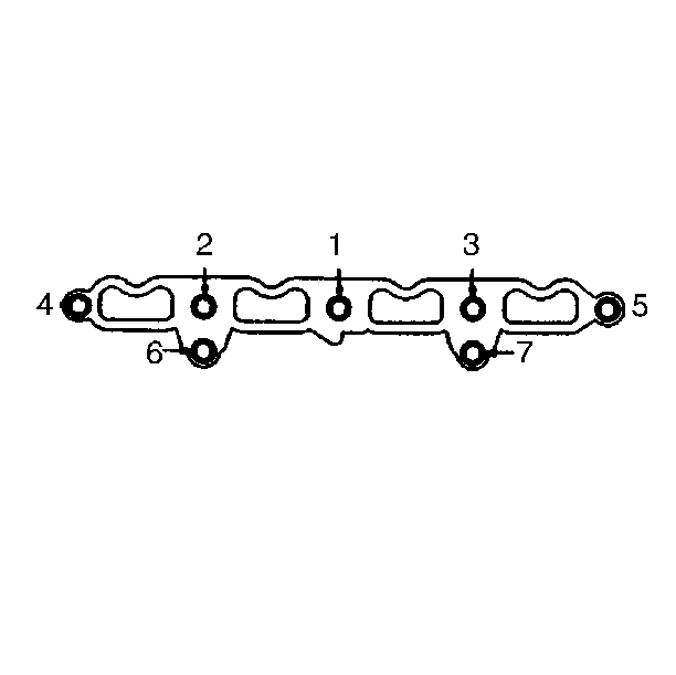
- Install the intake manifold nut and bolts.
Tighten
Tighten the nuts and bolts in sequence (1,2,3,4,5,6 and 7) to 24 N·m
(18 lb ft).
- Install wiring harness to retainer on bottom of intake.
- Install brake booster vacuum line to throttle body.

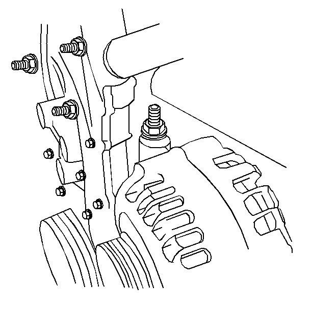
- Install the stud ended
generator mount bolt.
- Install the accelerator control cable bracket.
- Connect the vacuum hoses to the fuel regulator and to the EVAP
canister purge solenoid.
Important: If the IAT sensor is removed, apply sealant GM P/N 1052080
(Canadian P/N 10953480) or equivalent to its threads before installation.
- Connect the following electrical connections:
| • | EVAP canister purge solenoid |
- Install the air cleaner resonator and duct. Refer to
Air Cleaner Outlet Resonator Replacement
in Engine
Controls-2.4L.


