WIDE OPEN THROTTLE DRIVEABILITY HIGH AMBIENTS

Model and Year: 1987-88 B CAR WITH SEO 5.7L (VIN CODE 6) ENGINE
Some 1987 and 1988 B police cars equipped with 5.7L LM1 (Vin 6) engines may experience moderate to severe surge or a bog down on wide open throttle (WOT) acceleration at high ambient temperatures after either an extended hot idle or a hot soak (typically an hour or less). The condition is usually most noticeable at high engine RPM just prior to the WOT 1-2 shift. This condition may be addressed by installation of hot weather kit, P/N 10128259. This kit includes a carb blower fan, an in-tank electric fuel pump, and a modification to the carb bowl venting at WOT.
Parts are expected to be available on August 7, 1989. Until then normal part orders will not be accepted by GMSPO. Only verifiable emergency VIP orders will be accepted. SPO will make every effort to obtain parts. All parts will be placed on 400 control to waive VIP surcharges. However, the part will be shipped premium transportation at dealer's expense. All other order types will be canceled as incorrectly ordered while the 400 control is in place.
Service Procedure:
1. Drain the fuel tank.
2. Disconnect and remove the battery.
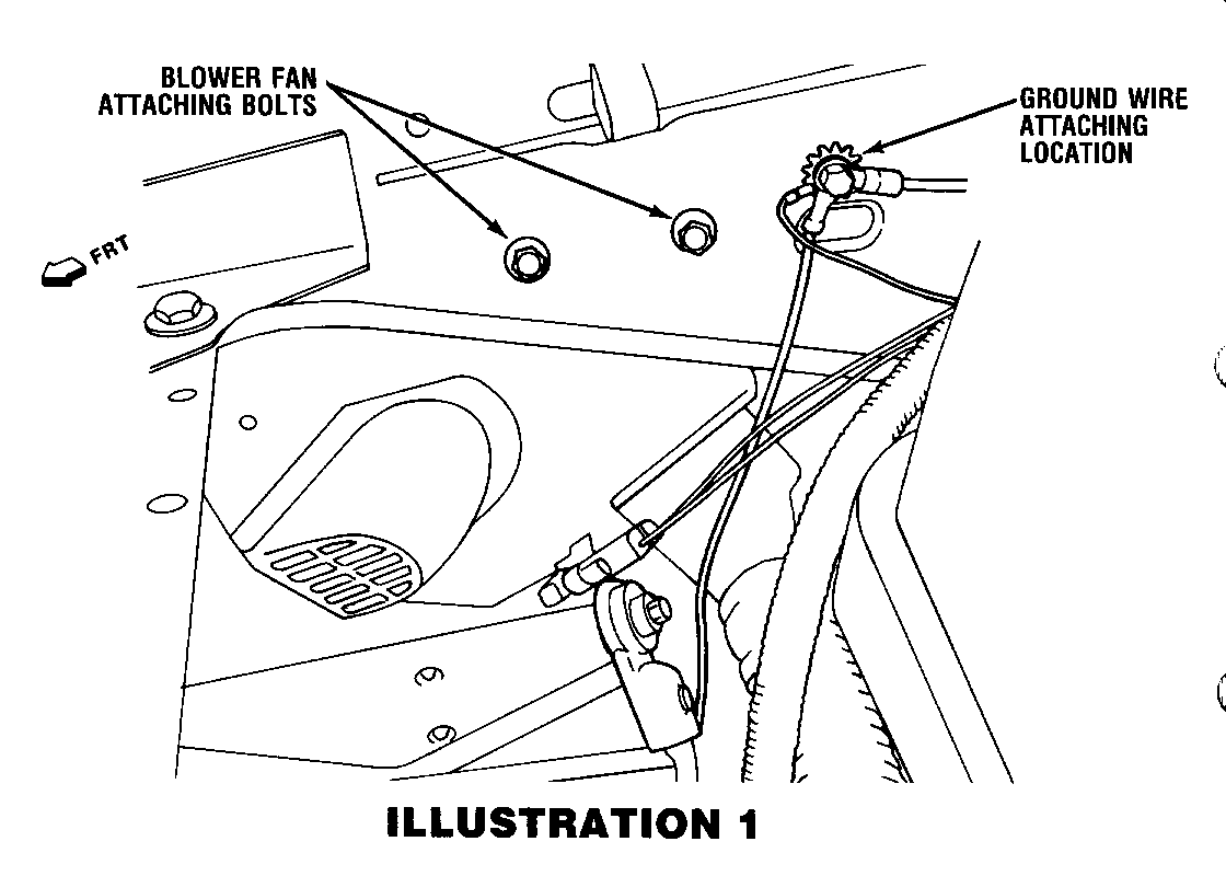
3. Install blower fan assembly in inner fender using two 7mm bolts as shown in Illustration #1.
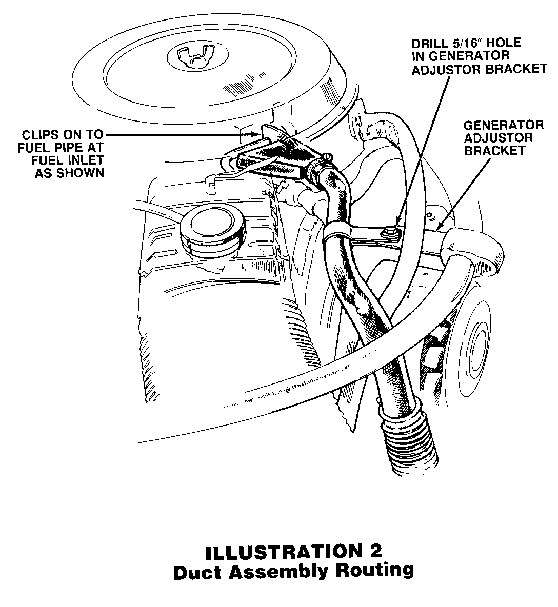
4. Temporarily connect duct to blower assembly and route as shown in Illustration #2. Clip on to carb fuel inlet pipe as shown.
5. Mark location of support strap slot on generator adjustor bracket. Remove duct.
6. Drill 5/16 inch hole in marked location on generator adjustor bracket.
7. Reconnect blower duct to blower assembly and route as shown in illustration #2.
8. Remove existing fuel sending unit from tank.
9. Install supplied sending unit with electric 3 psi booster pump.
10. Reinstall the tank with the sending unit wiring harness facing rearward.
11. Plug the sending unit wiring harness into the 3 pin connector on the longest lead of the supplied wiring harness. Wires in this 3 pin connector are black (ground), short green lead (sending unit signal) and tan (fuel pump power).
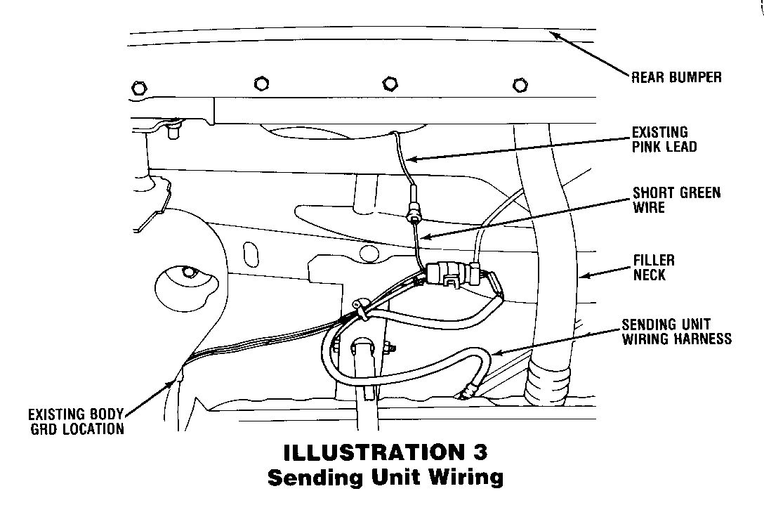
12. Connect the short green lead to the existing pink wire formerly connected to the old sending unit. See illustration #3.
13. Connect the bolt lug with two black wires going to it, to the body ground on the inside rear of the left hand frame rail. (Also shown on Illustration #3).
14. Route the wiring harness around the left hand side of the fuel tank and tie wrap at the tank strap attaching point.
15. Route the wiring harness above the rear axle following the path of the fuel lines and tie wrapping to the fuel lines as needed to assure retention.
16. Route the wiring harness down the inside of the left hand frame rail, following the path of the tank vent line pipe, and tie, wrapping it to the tank vent pipe near each of the points where the pipe is attached to the frame rail, continuing forward until just across from the oil filter.
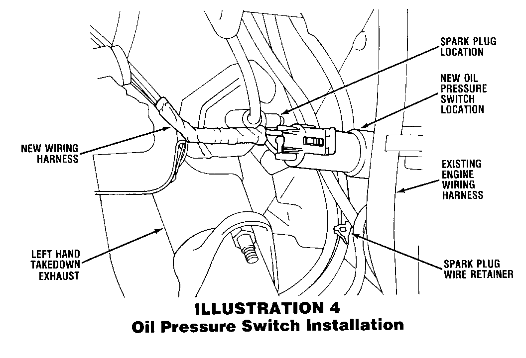
17. Remove the pipe plug located on the engine about 4 inches above the oil filter and install the oil pressure switch supplied in the kit. See Illustration #4.
18. Plug the two pin connector on the new harness into the oil pressure switch just installed.
19. Cut a small slit in the speedometer cable firewall grommet and feed the accelerator pedal switch wire (green wire on the new harness with a 2 pin edge connector and a short length of pink w/black stripe wire attached) through the firewall at this location. (Removal and re-attachment of the connector may make this easier.)
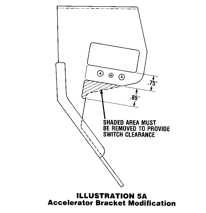
20. Remove the accelerator pedal bracket and modify by removing material as shown in Illustration #5A.
21. Reinstall the accelerator bracket.
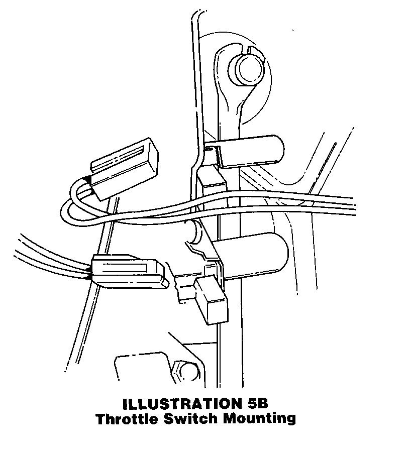
22. Cut a section from the hose supplied just long enough to cover the pawl on the supplied accelerator pedal switch (about an inch) and slide it onto the pawl.
23. Mount this accelerator pedal switch as shown in Illustration #5B.
24. Connect the 2 pin edge connector mentioned in step 19 to the accelerator pedal switch just installed.
25. Plug the short pink with black stripe lead into "IGN" ignition supply located just above the gage fuse in the fuse block.
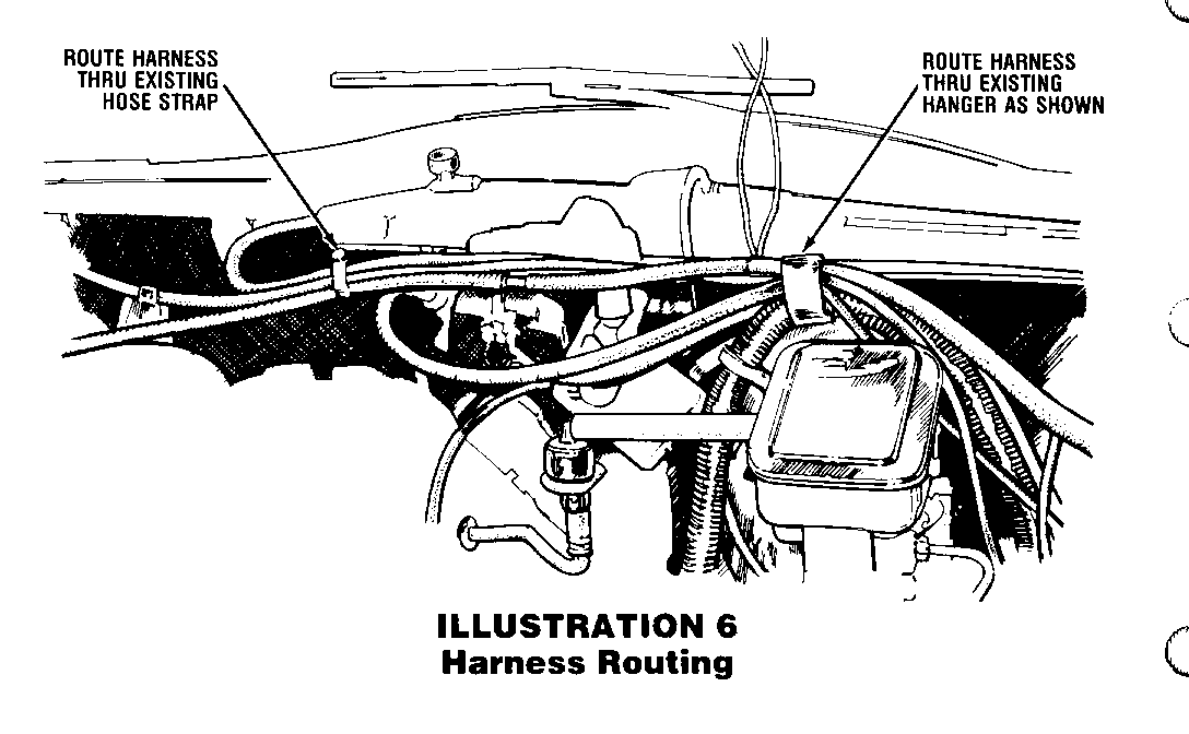
26. Returning under the hood, route the wiring harness up past the left hand side of the brake booster and through the harness clip above the brake booster which currently holds an existing harness and the windshield washer fluid supply line. See Illustration #6.
27. Route the harness over the top of the windshield wiper motor housing and tie wrap it to the windshield washer fluid supply line.
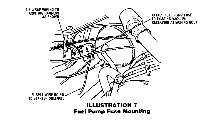
28. Route the harness past the AC vacuum reservoir and tie wrap it to the existing wiring harness just forward of the reservoir as shown in Illustration #7.
29. Mount the in-line fuel pump fuse (has purple wire and tan with white stripe wire going to it) under the attaching bolt for the existing wire harness as shown in illustration #7.
30. Connect the purple wire from this fuse to the starter solenoid.
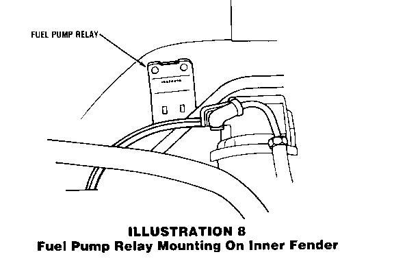
31. Mount the fuel pump relay on the right hand side inner fender as shown in Illustration #8.
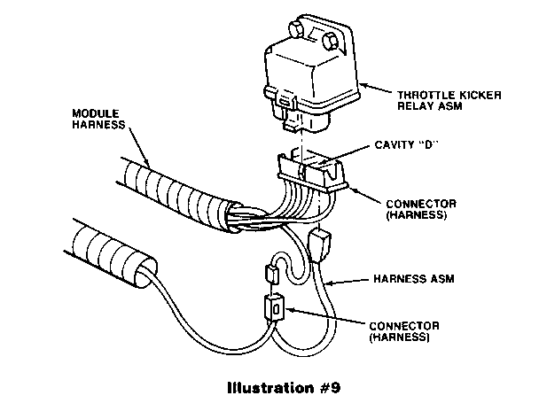
32. Unplug the existing fast idle (AC kicker) relay, unclip the side of the plug and remove pin D. In its place, install the lone pink/black stripe wire (has correct pin on it) and reconnect the fast idle relay. See illustration #9.
33. Install the wire removed from pin D (in step 32 above) into the single cavity connector supplied and plug into the connector about three inches upstream on the pink with black stripe wire mentioned in step 32 above. (Also shown in Illustration #9.)
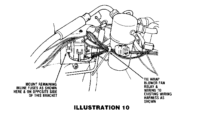
34. Tie wrap the blower fan relay to a convenient location on the harness as shown in Illustration #10.
35. Mount the two remaining in-line fuses to the multipurpose bracket as shown in illustration #10.
36. Connect the two pin connector (containing a green wire and a black with red stripe wire) to the carb fan blower connector.
37. Connect the black wire from the harness near the blower connector to the existing ground screw on the inner fender as shown in Illustration #1.
38. Connect the lone red wire (8-10 inches from the fan connector) to the existing 12 volt supply in the red box mounted on the right hand inner fender.
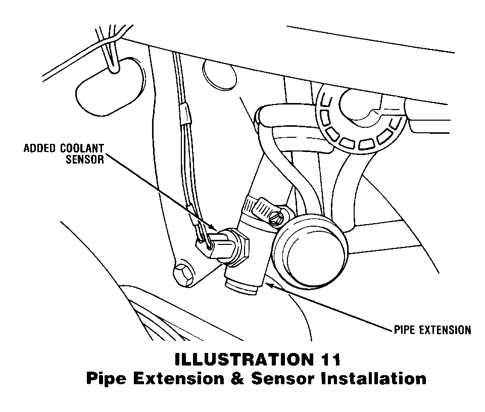
39. Install the pipe extension in the coolant line at the water pump as shown in illustration #11.
40. Install the supplied coolant temperature switch in the pipe extension just installed. (Also shown in illustration #11.)
41. Connect the wiring harness to coolant temperature switch just installed.
42. Cut the existing bowl vent hose several inches from the carburetor and install the supplied 3/8 x 3/8 x 3/8 tee into the line. (Connecting both cut lines with one port remaining open.)
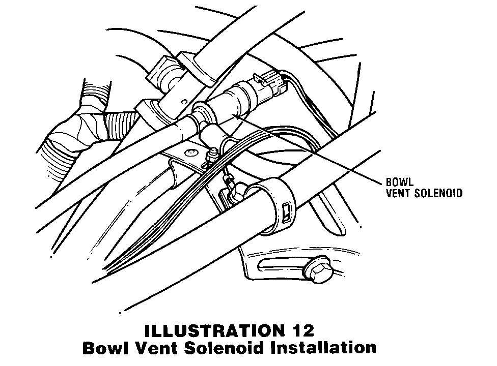
43. Install the supplied hose on the remaining port on the tee and locate the bowl vent solenoid (connected to it) as shown in Illustration #12.
44. Connect the wiring harness connector to the bowl vent solenoid.
45. Connect the ground wire (near the solenoid) to the generator bracket. (Also shown in illustration #12).
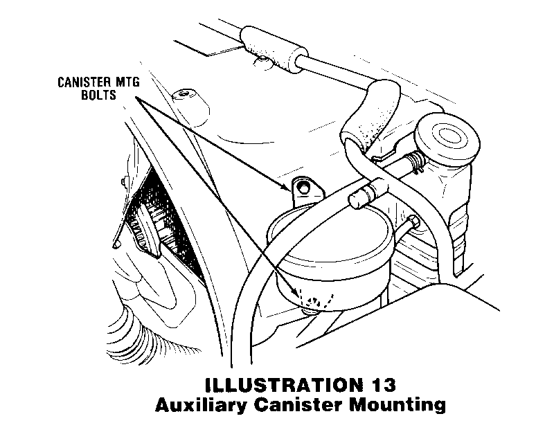
46. Install the 300cc auxiliary charcoal mini-canister by drilling two holes and mounting vertically on the plastic fan shroud as shown in Illustration #13 with the two bolts/nuts supplied.
47. Connect the remaining hose from the bowl vent solenoid to the port on the bottom of the charcoal mini-canister just installed.
48. Reinstall and reconnect the battery.
Labor Operation Number: T1424
Labor Time: 1.9 Hours
General Motors bulletins are intended for use by professional technicians, not a "do-it-yourselfer". They are written to inform those technicians of conditions that may occur on some vehicles, or to provide information that could assist in the proper service of a vehicle. Properly trained technicians have the equipment, tools, safety instructions and know-how to do a job properly and safely. If a condition is described, do not assume that the bulletin applies to your vehicle, or that your vehicle will have that condition. See a General Motors dealer servicing your brand of General Motors vehicle for information on whether your vehicle may benefit from the information.
