Info - Decreased Propeller Shaft Service Life

| Subject: | Decreased Propeller Shaft Service Life |
| Models: | 1998-2002 Chevrolet Camaro (EXPORT VEHICLES ONLY) |
| with 3800 V6 Engine (VIN K - RPO L36) |
Frequent and constant high speed operation of this vehicle may shorten the service life of the center support bearing in the two-piece driveshaft.
The driveshaft used in the 3800 V6-equipped vehicle is a two-piece unit which was designed with the power output and expected cruising speeds of the V6 engine in mind. Actual usage of V6-equipped vehicles has been at higher speeds combined with longer durations than expected. When replacement of the driveshaft is necessary, replace the driveshaft with the one-piece design used in the V8-equipped vehicles.
Service Procedure
Important: The two-piece propeller shaft and the support bearing used with the 3800 (VIN K) engine are not serviceable separately. The propeller shaft and the support bearing should be replaced as a complete assembly only.
Removal Procedure
- Raise and support the vehicle.
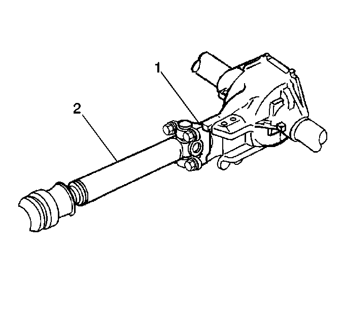
- Mark the relationship of the propeller shaft (2) to the pinion gear yoke (1).
- Place an adjustable stand under the propeller shaft near the support bearing in order to support the propeller shaft.
- Remove the bolts (4) from the support bearing (3).
- Remove the following components from the torque arm (2):
- Remove the propeller shaft bolts (2).
- Remove the propeller shaft retainers (1).
- Perform the following steps in order to remove the propeller shaft:
- Inspect the transmission output shaft splines for burrs.
- Inspect the outer diameter of the slip yoke (1) for burrs.
- Inspect the splines of the slip yoke for the following conditions:
- Inspect the relationship of the splines of the slip yoke to the transmission output shaft splines. The splines of the slip yoke must meet the following conditions:
- Inspect the pinion gear yoke (1) at the universal joint cap mating surface for the following conditions:
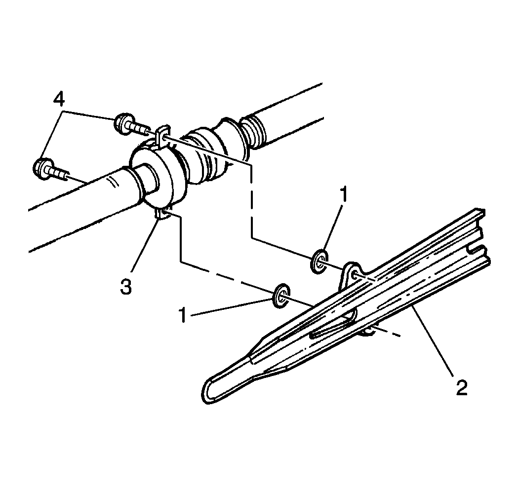
| • | The support bearing (3) |
| • | The washers (1) |
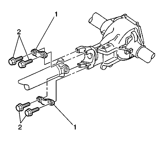
Important: Support the propeller shaft during removal.
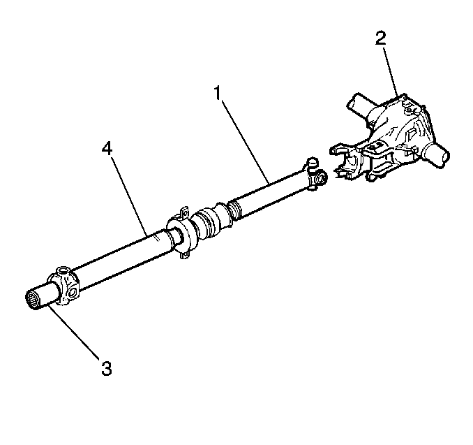
| 8.1. | Withdraw the slip yoke (3) from the transmission. |
| 8.2. | Move the propeller shaft (1 and 4) rearward and pass the propeller shaft under the housing (2). |
If the bearing caps are loose, tape the bearing caps together in order to prevent the loss of the needle roller bearings.
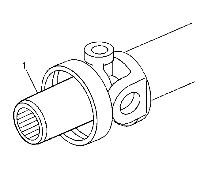
| • | Damage |
| • | Twisting |
| • | Wear |
| • | The slip yoke splines and the transmission output shaft splines are of equal number. |
| • | The slip yoke splines and the transmission output shaft splines must engage properly. |
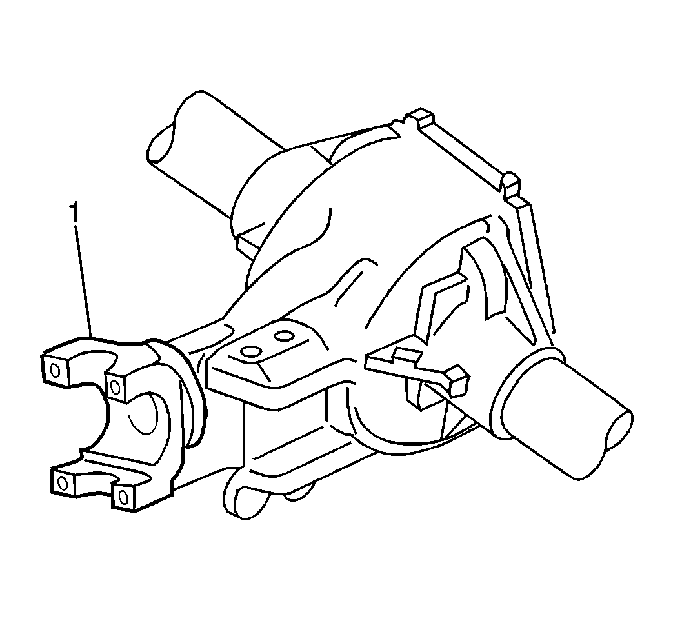
| • | Burrs |
| • | Foreign material |
Installation Procedure
- Lubricate the slip yoke with chassis lubricant.
- Install the slip yoke onto the transmission output shaft.
- Install the rear of the propeller shaft (2) to the pinion gear yoke (1).
- Install the rear universal joint to the pinion gear yoke.
- Install the propeller shaft retainers (1).
- Install the propeller shaft bolts (2).
- Lower the vehicle.
Important: Align the reference marks on the propeller shaft with the reference marks on the pinion yoke to ensure the proper propeller shaft/pinion yoke relationship.
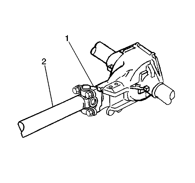
Ensure that the bearing caps are properly seated.

Notice: Use the correct fastener in the correct location. Replacement fasteners must be the correct part number for that application. Fasteners requiring replacement or fasteners requiring the use of threadlocking compound or sealant are identified in the service procedure. Do not use paints, lubricants or corrosion inhibitors on fasteners or fastener joint surfaces unless specified. These coatings affect fastener torque and joint clamping force and may damage the fastener. Use the correct tightening sequence and specifications when installing fasteners in order to avoid damage to parts and systems.
Tighten
Tighten the propeller shaft bolts evenly to 22 N·m (16 lb ft).
Parts Information
Part Number | Description | Qty |
|---|---|---|
12568188 | Shaft, Propeller | 1 |
Parts are currently available from GMSPO Europe.
Warranty Information
For vehicles repaired under warranty, use:
Labor Operation | Description | Labor Time |
|---|---|---|
F1280 | Propeller Shaft Assembly -- Replace Two Piece Design with One-Piece | 0.5 hr |
