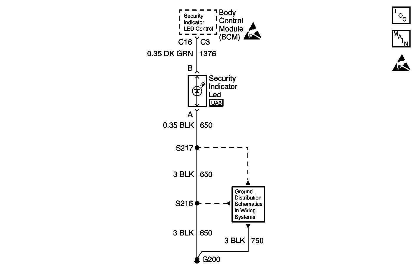
Circuit Description
The body control module (BCM) provides an output on circuit 1376 to the security LED.
Conditions for Setting the DTC
DTC 25 is set when the BCM detects the security LED at connector C3 terminal C16 when the ignition is turned to the RUN position.
DTC 35 is set when the BCM detects the security LED at any time since the codes were last cleared.
Action Taken When the DTC Sets
DTC 35 is required for content theft deterrent operation. The security LED must be detected for the alarm to function.
Test Description
The numbers below refer to the step numbers on the diagnostic table.
-
This step tests the security LED ground circuit 650.
-
This step tests the security LED.
-
This step tests circuit 1376 for an open or poor connection.
Step | Action | Value(s) | Yes | No |
|---|---|---|---|---|
DEFINITION: Perform this diagnostic when DTC 25/35 is not set or if the LED is not functioning. | ||||
1 | Did you perform the Diagnostic System Check? | -- | ||
Does the test lamp illuminate? | -- | |||
Using a DMM set to the diode scale, connect the red test lead to terminal B of the security LED and the black test lead to terminal A. Refer to Circuit Testing in Wiring Systems. Does the security LED illuminate? | -- | |||
4 | Repair the open in circuit 650 between S217 and the security LED. Refer to Wiring Repairs in Wiring Systems. Did you complete the repair? | -- | System OK | -- |
Test for and repair a poor connection in circuit 1376 between the body control module (BCM) and the security LED. Refer to Testing for Intermittent Conditions and Poor Connections and Connector Repairs in Wiring Systems. Did you find and repair a poor connection? | -- | System OK | ||
6 |
Did you complete the replacement? | -- | System OK | -- |
7 |
Important: Perform the set up procedure for the body control module. Replace the BCM. Refer to Body Control Module Replacement in Body Control System. Did you complete the replacement? | -- | System OK | -- |
