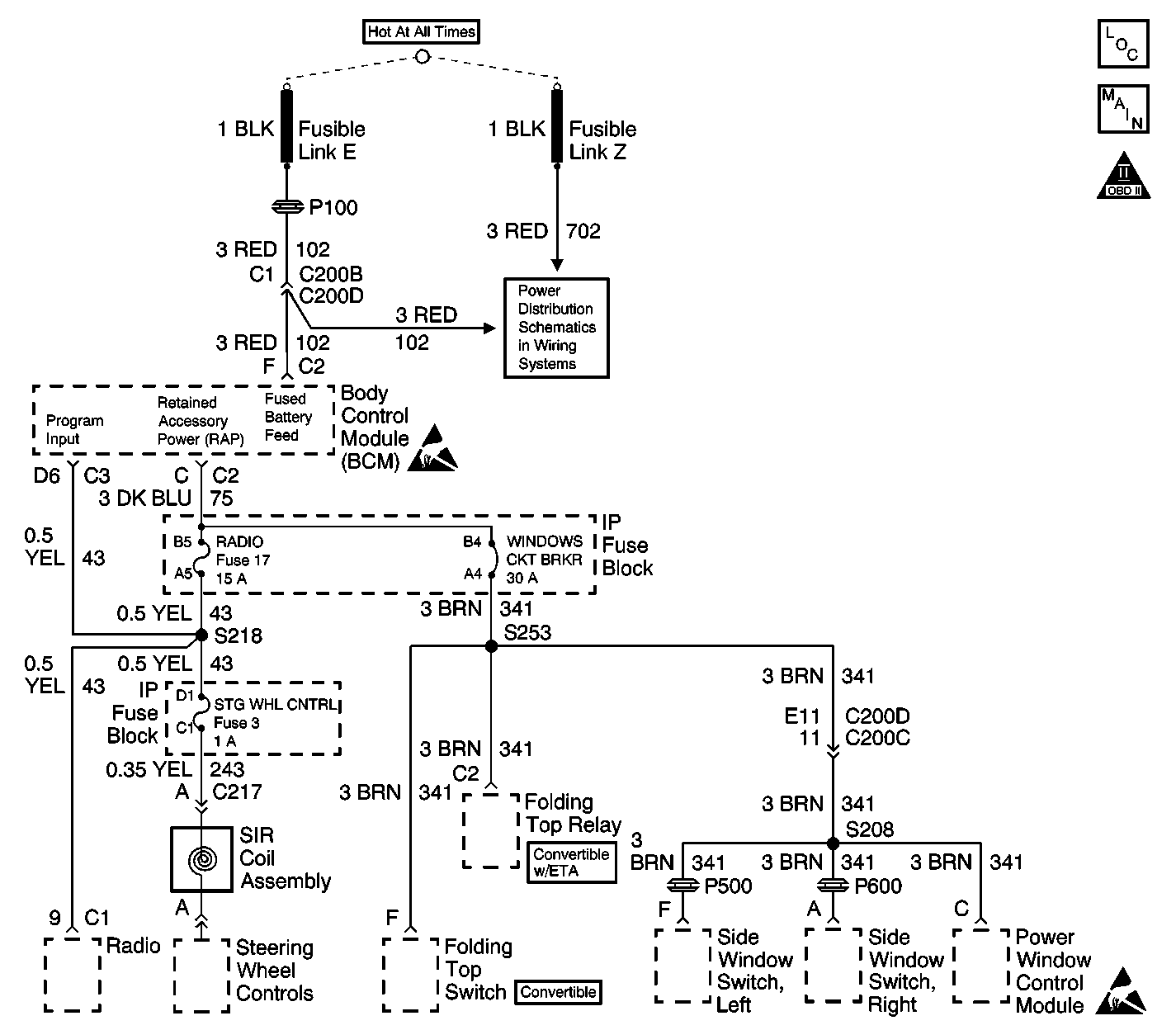
Circuit Description
The body control module (BCM) retained accessory power (RAP) function is enabled when the ignition switch is turned to the RUN position. The RAP allows the operation of the following components for up to 10 minutes after the ignition switch is turned to the OFF position:
| • | The power windows |
| • | The radio and the steering wheel controls |
| • | The folding top |
| • | The rear fog lamps (export only) |
The RAP is immediately disabled if any door is opened. The BCM provides the RAP function through circuit 75 to the following components:
| • | The WINDOWS circuit breaker |
| • | The RADIO Fuse 17 |
Conditions for Setting the DTC
| • | Circuit 75 is shorted to ground for more than 50 milliseconds while the RAP is enabled. |
| • | Circuit 75 is shorted to B+ for more than 50 milliseconds while the RAP is disabled. |
| • | Circuit 102 is open. |
Action Taken When the DTC Sets
| • | The RAP feature will not function if circuit 75 is shorted to ground. |
| • | The RAP feature will not deactivate when the door is opened if circuit 75 is shorted to B+. |
| • | The BCM will read out a series of flash codes upon entering the diagnostic mode. |
Conditions for Clearing the DTC
The fault is corrected and the DTC memory clearing procedure is completed.
Diagnostic Aids
If the only DTC that flashes is a HISTORY code (DTC 33), the problem may be intermittent. Perform the test shown while "wiggling" the wiring and connectors. This can often cause the fault to appear. Test for poor connections at the BCM connector, which could cause an open or an intermittent fault. Refer to Diagnostic Trouble Code (DTC) Displaying Displaying DTCs .
Test Description
The numbers below refer to the step numbers on the diagnostic table.
-
This step tests for an open in circuit 102 between C200D and the BCM.
-
This step determines if the radio operates. The radio may not work due to a short to ground in circuit 75 or a defective BCM.
-
This step determines if there is a short in either circuit 43 or circuit 243. A short in either circuit 43 or circuit 243 would allow the radio to play with the ignition switch in the OFF position and a door open.
-
This step determines circuit 341 is shorted to battery voltage.
Step | Action | Value(s) | Yes | No |
|---|---|---|---|---|
1 | Did you perform the RAP Diagnostic System Check? | -- | ||
Connect a DMM between the body control module (BCM) connector C2 terminal F and ground. Refer to Circuit Testing in Wiring Systems. Does the meter read 12 VDC? | 12 VDC | |||
3 | Repair the open in circuit 102 between C200D and the BCM. Refer to Wiring Repairs in Wiring Systems. Is the repair complete? | -- | System OK | -- |
Does the radio operate? | -- | |||
Does the radio operate? | -- | |||
6 | Repair the short to battery voltage in circuit 43/243. Refer to Wiring Repairs in Wiring Systems. Is the repair complete? | -- | System OK | -- |
Does the power window operate? | -- | |||
8 | Repair the short to battery voltage in circuit 341. Refer to Wiring Repairs in Wiring Systems. Is the repair complete? | -- | System OK | -- |
9 | Test for and repair a short to battery voltage in circuit 75. Refer to Circuit Testing and Wiring Repairs in Wiring Systems. Did you find and repair a short? | -- | System OK | |
10 | Test for and repair a short to ground in circuit 75. Refer to Circuit Testing and Wiring Repairs in Wiring Systems. Did you find and repair a short? | -- | System OK | |
11 |
Important: Perform the set up procedure for the body control module (BCM). Replace the BCM. Refer to Body Control Module Replacement in Body Control System. Did you complete the replacement? | -- | System OK | -- |
