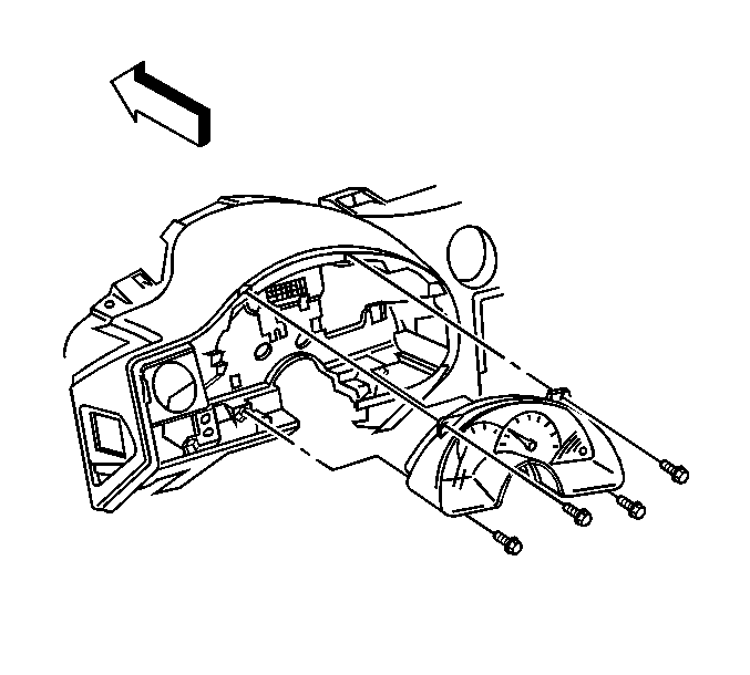
For 1990-2009 cars only
Tools Required
Removal Procedure
- Remove the IP cluster bezel. Refer to Instrument Panel Cluster Trim Plate Bezel Replacement .
- Remove the instrument cluster bolts.
- Remove the instrument cluster.

Gently pull the cluster straight out in order to disconnect the electrical connector.
Installation Procedure
- Align the instrument cluster to the IP carrier alignment pins.
- Install the instrument cluster bolts.
- Install the IP cluster bezel. Refer to Instrument Panel Cluster Trim Plate Bezel Replacement .
- Synchronize the IP cluster. Refer to the following procedure:

Tighten
Tighten the instrument cluster bolts to 2.2 N·m (19 lb in)
in the following sequence:
| 2.1. | Upper left |
| 2.2. | Lower right |
| 2.3. | Upper right |
| 2.4. | Lower left |
Instrument Panel Cluster Synchronization
When installing a new IP cluster it must be synchronized to the supplemental inflatable restraint (SIR) module in order to synchronize the new cluster, perform the following steps:
- Connect the Scan Tool to the data link connector (DLC).
- Proceed to the SPECIAL FUNCTIONS key under INSTRUMENT PANEL CLUSTER.
- Select the SYNCHRONIZE IPC and SIR key.
- The screen will display: IPC and SIR modules-Now synchronizing modules.
- If the procedure is completed successfully the screen will display: Module Synchronization Complete.
- If communication is lost with the SIR or IPC, the screen will display: Loss of Communications with Vehicle - Check Diagnostics Link Connector - Check Ignition (On/Off).
