For 1990-2009 cars only
Removal Procedure
Tools Required
- Disconnect the negative battery cable.
- Remove the serpentine belts from crankshaft pulley.
- Using 28 mm socket, remove the crankshaft harmonic balancer retaining bolt.
- Remove the crankshaft harmonic balancer using J 38197-A
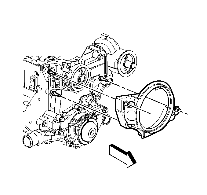
- Remove the crankshaft position sensor shield. Do Not use a pry bar.
- Disconnect the sensor electrical connector.
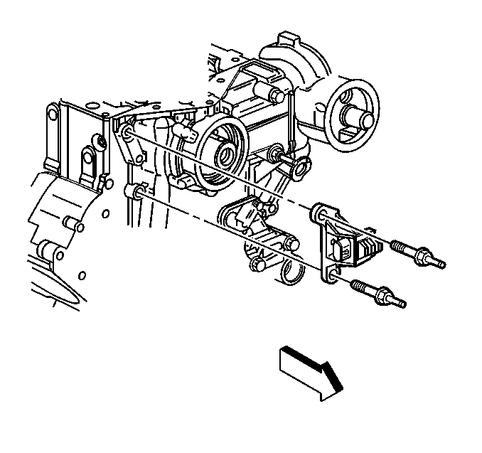
- Remove the sensor from the block face.

Installation Procedure
- Position the crankshaft position sensor onto the engine block face.
- Install the bolts to hold the sensor to the engine block face.
- Position and install the crankshaft position sensor shield.
- Connect the electrical connector.
- Position the balancer onto the crankshaft.
- Apply thread sealer GM-1052080 or equivalent to threads of crankshaft balancer bolt.
- Install the serpentine accessory drive belt.
- Connect the negative battery cable.
- Perform the Crankshaft Variation Learn Procedure. Refer to Crankshaft Position System Variation Learn

Notice: Use the correct fastener in the correct location. Replacement fasteners must be the correct part number for that application. Fasteners requiring replacement or fasteners requiring the use of thread locking compound or sealant are identified in the service procedure. Do not use paints, lubricants, or corrosion inhibitors on fasteners or fastener joint surfaces unless specified. These coatings affect fastener torque and joint clamping force and may damage the fastener. Use the correct tightening sequence and specifications when installing fasteners in order to avoid damage to parts and systems.
Tighten
Tighten bolts to 20-40 N·m (14-28 lb ft).
Tighten
Tighten bolt to 150 N·m +76 degrees(110 lb ft +76
degrees).
