Front Suspension

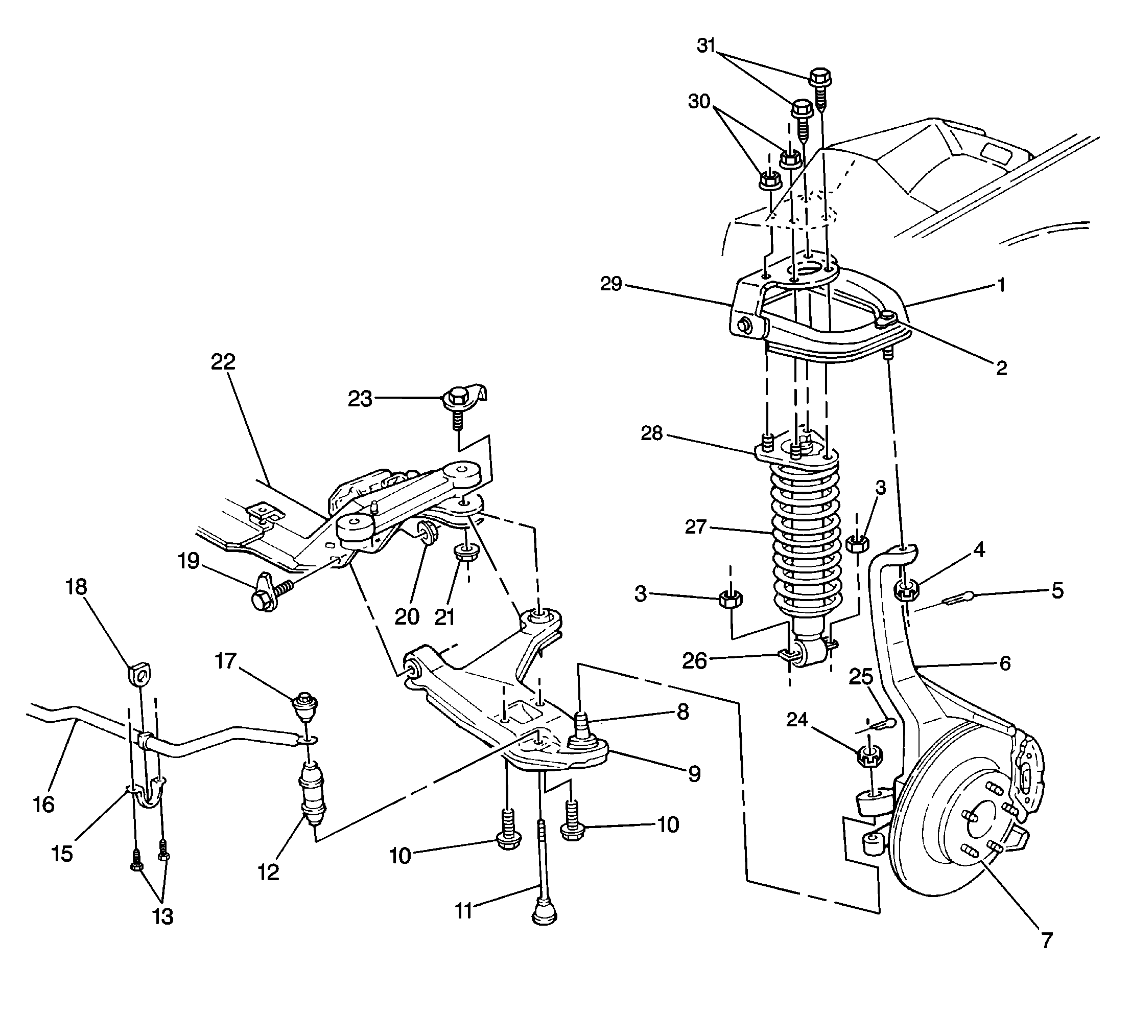
The short/long arm front suspension design allows each wheel to compensate for changes in the road surface level without appreciably affecting the opposite wheel. Each wheel independently connects to the frame by the following:
| • | A steering knuckle (6) |
| • | A wheel hub (7) |
| • | A shock absorber (26) and spring (27) |
| • | Upper and lower ball studs (2,8) |
| • | Upper and lower control arms (1,9) |
The steering knuckle and the hubs (6,7) move in a prescribed three-dimensional arc. The front wheels are held in proper relationship to each other by the two front tie rods. The front tie rods connect to the steering arms on the knuckles and connect to the steering gear.
Springs (27) mount to the lower control arms (9). Direct-acting shock absorbers (26) provide ride control. The upper portion of the shock absorber connects to the front upper shock absorber mount (28). The upper mount (28) extends through the upper control arm support (29) and through the center wheelhouse. The upper mount attaches with two bolts/screws (31) and two nuts (30).
The stabilizer shaft (16) controls idle roll of the front suspension. The stabilizer shaft mounts to the stabilizer shaft insulators (18). These insulators attach to the frame side rails by the stabilizer shaft brackets. The ends of the stabilizer shaft (16) connect to the lower control arms (9) by the stabilizer shaft links (11). These ends are isolated by bushings.
The inner ends of the lower control arm (9) have pressed-in bushings. Bolts (19) pass through the bushings and attach the lower control arm (9) to the crossmember (22).
The upper ball stud (2) is riveted to the upper control arm (1). This stud attaches to the steering knuckle (6) with a nut (4) and a cotter pin (5). The control arm bolts to the shock absorber (26) through an upper control arm support (29) which attaches to the body.
The lower ball stud (8) is press fit into the lower control arm (9). This ball stud attaches to the steering knuckle (6) with a nut (24) and a cotter pin (25).
Rubber seals are provided at the ball sockets in order to keep dirt and moisture from entering the stud and damaging the bearing surfaces.
