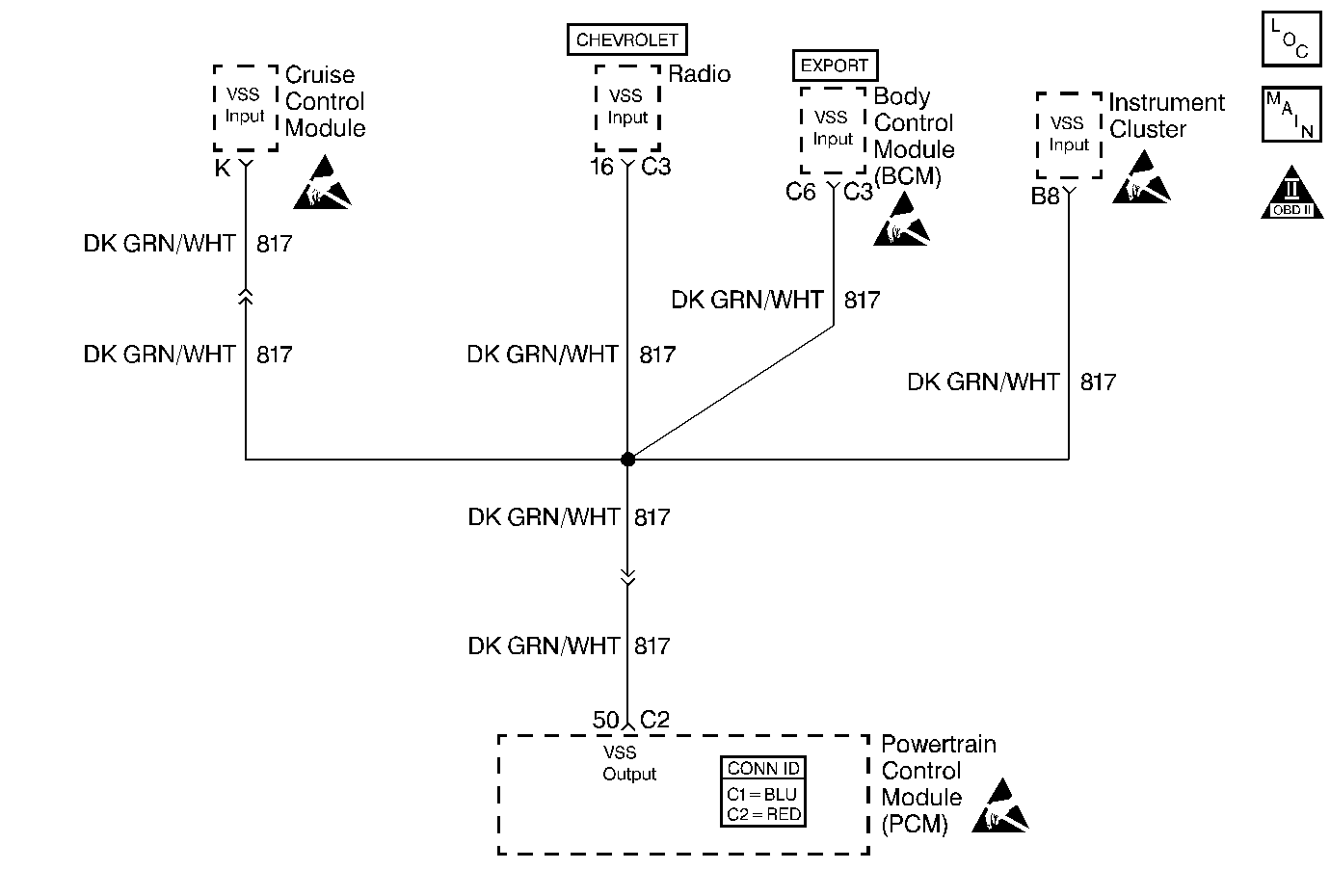
Circuit Description
Various components apply a voltage to the Vehicle Speed Output circuit. The PCM creates the Vehicle Speed Output signal by rapidly grounding this circuit via an internal switch called a driver. The driver operates at the same rate as the VSS signal input. The various components recognize the voltage being pulled to ground as an indication of vehicle speed.
The driver supplies the ground for the component being controlled. When the PCM commands a component ON, the voltage of the control circuit should be low (near 0 volts). When the PCM commands the control circuit to a component OFF, the voltage potential of the circuit should be high (near battery voltage).
Diagnostic Aids
Important:
• Remove any debris from the PCM connector surfaces before servicing
the PCM. Inspect the PCM connector gaskets when diagnosing/replacing the PCM.
Ensure that the gaskets are installed correctly. The gaskets prevent water
intrusion into the PCM. • For any test that requires probing the PCM or component harness
connectors, use the J 35616
connector test adapter kit. Using this kit prevents any damage to
the harness connector terminals. Refer to
Using Connector Test Adapters
in Wiring Systems.
Using Freeze Frame and/or Failure Records data may aid in locating an intermittent condition. If you cannot duplicate the condition, the information included in the Freeze Frame and/or Failure Records data can aid in determining how many miles since the condition occurred.
For an intermittent, refer to Symptoms .
Test Description
The numbers below refer to the step numbers on the diagnostic table.
Step | Action | Value(s) | Yes | No |
|---|---|---|---|---|
1 | Did you perform the Powertrain On-Board Diagnostic (OBD) System Check? | -- | ||
2 |
Important: If the IPC is completely inoperative, refer to Diagnostic System Check - Instrument Cluster in Instrument Panel, Gauges and Console.
Does the vehicles speedometer indicate vehicle speed? | -- | Go to Diagnostic Aids | |
Does the DMM indicate the specified value? | B+ | |||
4 |
Does the DMM indicate continuity? | -- | ||
Test the continuity of the Vehicle Speed Output circuit between the PCM harness connector and the I/P harness connector, using the DMM connected to battery ground. Refer to Testing for Continuity in Wiring Systems. Does the DMM indicate continuity? | -- | |||
6 |
Did you find and correct the condition? | -- | System OK | Go to Diagnostic System Check - Instrument Cluster in Instrument Panel, Gauges and Console |
7 | Repair the Vehicle Speed Output circuit for an open or short to ground. Refer to Wiring Repairs in Wiring Systems. Is the action complete? | -- | System OK | -- |
8 |
Did you find and correct the condition? | -- | System OK | |
9 |
Important:: Program the replacement PCM. Refer to Powertrain Control Module Replacement/Programming . Replace the PCM. Is the action complete? | -- | System OK | -- |
