CAMPAIGN: ENGINE HARNESS ECM CONNECTOR CRACKED TERMINAL

General Motors has determined that some 1987 Chevrolet S/T 10 model trucks equipped with 2.5L (RPO LN8) engines may have been built with an engine electrical harness which has a cracked wire teminal on a jumper wire in the ECM connector. As a part of the fuel injector signal circuit, if the teminal breaks and causes an open circuit, this will allow the engine to crank but not start.
To prevent this condition from occurring it will be necessary to replace the jumper wire, which has terminals attached.
VEHICLES INVOLVED
Involved are certain 1987 Chevrolet S/T 10 trucks equipped with 2.5L engines (RPO LN8) produced within the following VIN breakpoints:
PLANT FROM THROUGH ----- ---- ------- Pontiac West H0120345 H0126206 Moraine H2139134 H2151404 Shreveport H8141449 H8146252
Involved vehicles have been identified by Vehicle Identification Number Computer Listings. Computer listings contain the complete Vehicle Identification Number, owner name and address data, and are furnished to the involved dealers with the campaign bulletin. Owner name and address data furnished will enable dealers to follow-up with owners involved in this campaign.
These listings may contain owner names and addresses obtained from State Motor Vehicle Registration Records. The use of such motor vehicle registration data for any other purpose is a violation of law in several states. Accordingly, you are urged to limit the use of this listing to the follow-up necessary to complete this campaign. Any dealer not receiving a computer listing with the campaign bulletin has no involved vehicles currently assigned.
OWNER NOTIFICATION
Owners will be notified of this campaign on their vehicles by Chevrolet Motor Division (see copy of Owner Letter included with this bulletin).
DEALER CAMPAIGN RESPONSIBILITY
Dealers are to service all vehicles subject to this campaign at no charge to owners, regardless of mileage, age of vehicle, or ownership, from this time forward.
Whenever a vehicle subject to this campaign is taken into new or used Vehicle inventory, or it is in vour dealership for service in the future, you should take the steps necessary to be sure the campaign correction has been made before reselling or releasing the vehicle.
Owners of vehicles recently sold from your new vehicle inventory are to be contacted by the dealer, and arrangements made to make the required correction according to instructions contained in this bulletin.
PARTS INFORMATION
Jumper wires complete with teminals have been shipped directly to the involved dealers. If additional wires are required, contact your Chevrolet Branch Office.
PART NUMBER DESCRIPTION QUANTITY ------------ ----------- ------- 12077137 Jumper Wire 1
SERVICE PROCEDURE
A jumper wire will be furnished "no charge" for each vehicle by Chevrolet. Parts will be shipped directly to the involved dealers. Use the following instructions to install the new jumper wire. In order to remove micro-pack terminals from the connector, a terminal removal tool will be required to perform this repair. Proper tool is Kent-Moore J-33095 or Burroughs BT-8234-A.
1. Disconnect negative battery cable.
2. Locate the ECM under the instrument panel on the passenger side of the vehicle. Disconnect both connectors from the ECM.
3. Locate and disconnect the instrument panel wiring interconnect taped to ECM harness.
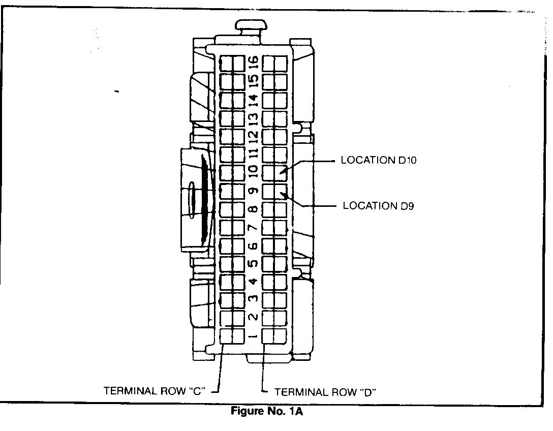
a. Locate the 151 Jumper wire terminals (.80 gage black) that are side by side in cavities D-9 and D-10 in the center of the 32-way ECM connector (with gray secondary locks), Figure No. 1A.
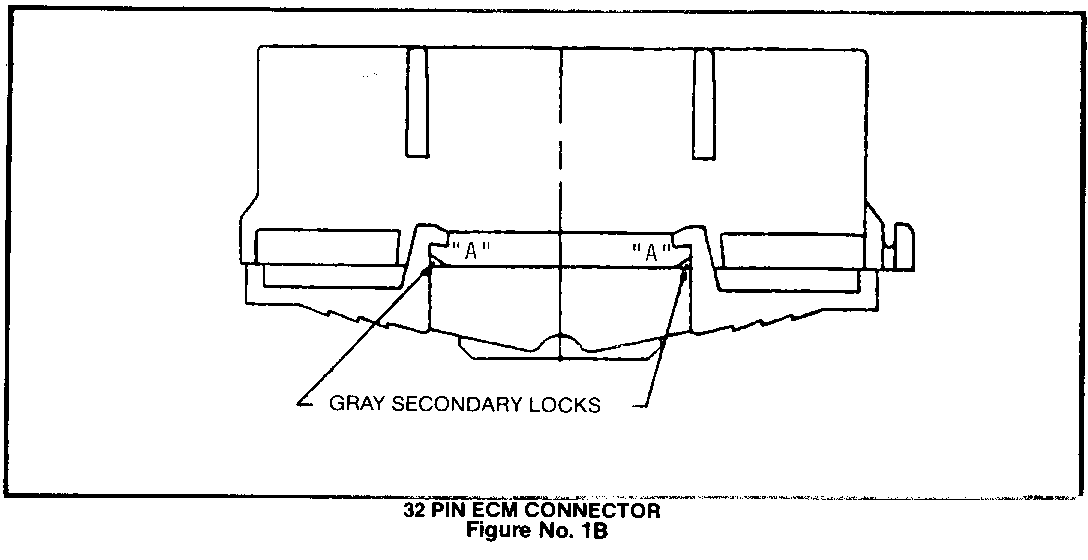
4. Remove the gray comb secondary lock (using a pick) retaining the 151 wire terminal by releasing the lock tangs on the outside of the ECM connector at both points A and pulling the secondary lock out of the connector (Figure No. 1B).
Removal of the 151 wire:
a. Grasp the wire seated in cavity D-9 and pushthe terminal to its forward most position.
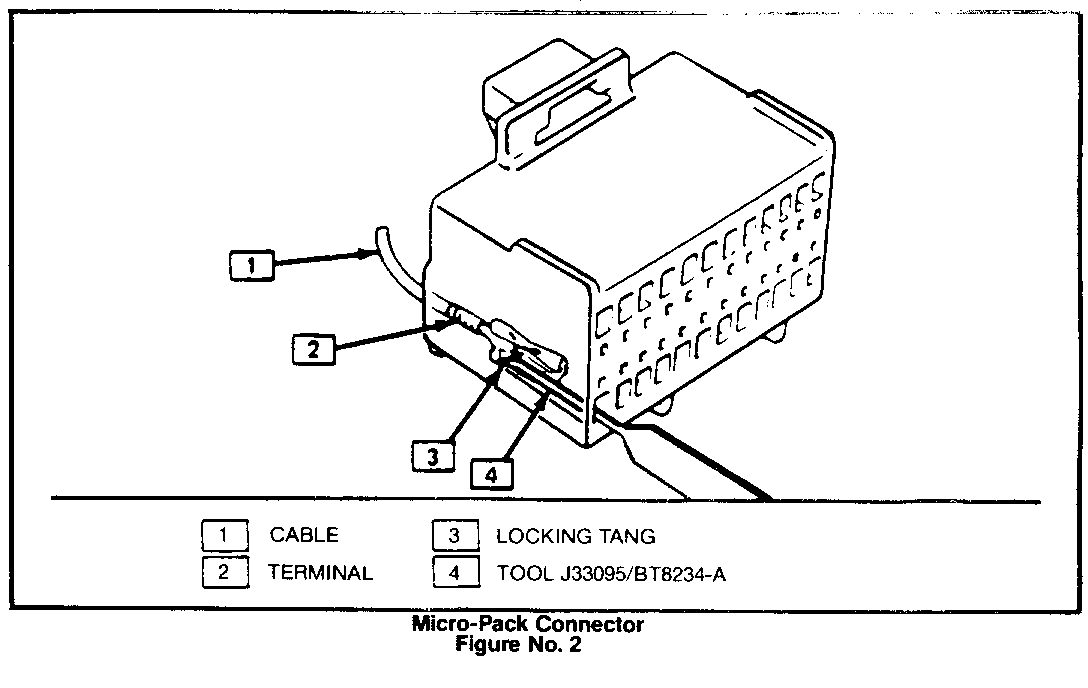
b. Insert the micro-pack removal tool into the outside hole of the D-9 cavity (see Figure No. 2). Removal tool will depress the lock tang only while the terminal is in the forward most position in the cavity.
c. While holding the tool securely in place, gently pull on the wire to remove the terminal.
CAUTION
- To prevent damage to the connector: A. Only use the micro-pack removal tool, J-33095 or BT-8234-A. B. Do not apply excessive pressure to the removal tool. C. Do not rock or angle the removal tool.
d. Remove the second end of the 151 wire by repeating steps 4a through 4c in cavity D-10.
Remove the 151 wire from the harness by firmlygrasping both ends with pliers and gently pulling it out of the harness. Install the replacement wire as follows:
Orient the first teminal on the replacement wire so that the box side of the terminal is toward the center of the connector. Insert the terminal into cavity number D-9. A faint click will be heard as the terminal locks in place. Give the wire a light tug to insure it is seated.
Install the remaining end of the replacement wire into cavity D-10 following the above procedure.
Reinstall the secondary lock into the connector by inserting the teeth of the lock into the connector and pushing fimly until the lock legs snap into place.
Separate the two ECM connector branches. Fold the loop of the replacement wire toward the 32-way ECM connector and secure with plastic electrical tape.
Reconnect the two ECM connectors to the ECM. Reconnect the instrument panel interconnect.
5. Reconnect battery cable. 6. Install Campaign Identification Label.
CAMPAIGN IDENTIFICATION LABEL
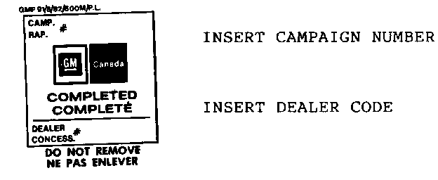
Each vehicle corrected in accordance with the instructions outlined in this Product Campaign Bulletin will require a "Campaign Identification Label." Each label provides a space to include the five digit dealer code of the dealer performing the campaign service. This information may be inserted with a typewriter or ballpoint pen.
Each "Campaign Identification Label" is to be located on the radiator core support in an area which will be visible when the vehicle is brought in for periodic servicing by the owner.
Apply "Campaign Identification Label" only on a clean dry surface.
CLAIM INFORMATION
Submit a Product Campaign Claim with the information indicated below:
* FAILED PARTS LABOR LAB OTH REPAIR PERFORMED PC PART NO. ALLOW FC OP HRS HRS ---------------- -- -------- ----- --- -- --- --- Replace Jumper Wire 00 V4040 0.5 0.1
* Campaign Administrative Allowance
Dealers will automatically receive the correct labor and material allowance based on the labor operation performed.
Refer to the Chevrolet Claims Processing Manual for details on Product Campaign Claim submission.


General Motors bulletins are intended for use by professional technicians, not a "do-it-yourselfer". They are written to inform those technicians of conditions that may occur on some vehicles, or to provide information that could assist in the proper service of a vehicle. Properly trained technicians have the equipment, tools, safety instructions and know-how to do a job properly and safely. If a condition is described, do not assume that the bulletin applies to your vehicle, or that your vehicle will have that condition. See a General Motors dealer servicing your brand of General Motors vehicle for information on whether your vehicle may benefit from the information.
